Integrated ball cage

a ball cage and ball bearing technology, applied in the direction of printers, instruments, camera focusing arrangements, etc., to achieve the effect of reducing manufacturing and assembly costs

Inactive Publication Date: 2012-09-20
RPX CORP
View PDF0 Cites 9 Cited by
  • Summary
  • Abstract
  • Description
  • Claims
  • Application Information

AI Technical Summary

Benefits of technology

[0022]In accordance with the objects of this invention a method to reduce manufacturing and assembly costs for measures to avoid blocking ball conditions for linear ball bearings has been achieved. The method comprises the following steps, firstly: (1) providing a camera module wherein movements of a lens barrel are driven by at least one linear actuator and are guided by a first and a second ball bearing, (2) inserting each ball of the ball bearings in an own integrated ball cage, which is integrated in the moving lens barrel, and (3) selecting for the first ball bearing a fixed ball bearing, wherein ball bearing contact points are shifted by a small angle in direction of a preload force applied to the first ball bearing. Furthermore the method comprises (4) selecting for the second ball bearing a non-locating ball bearing, (5) deploying each ball bearing in a suitable position in order to be able to receive the preload force, and (6) providing the preload force towards the bearings in order to hold the beari

Problems solved by technology

It is a challenge for engineers to find solutions to avoid blocking ball con

Method used


Image

  • Integrated ball cage
  • Integrated ball cage
  • Integrated ball cage

Examples


Embodiment Construction

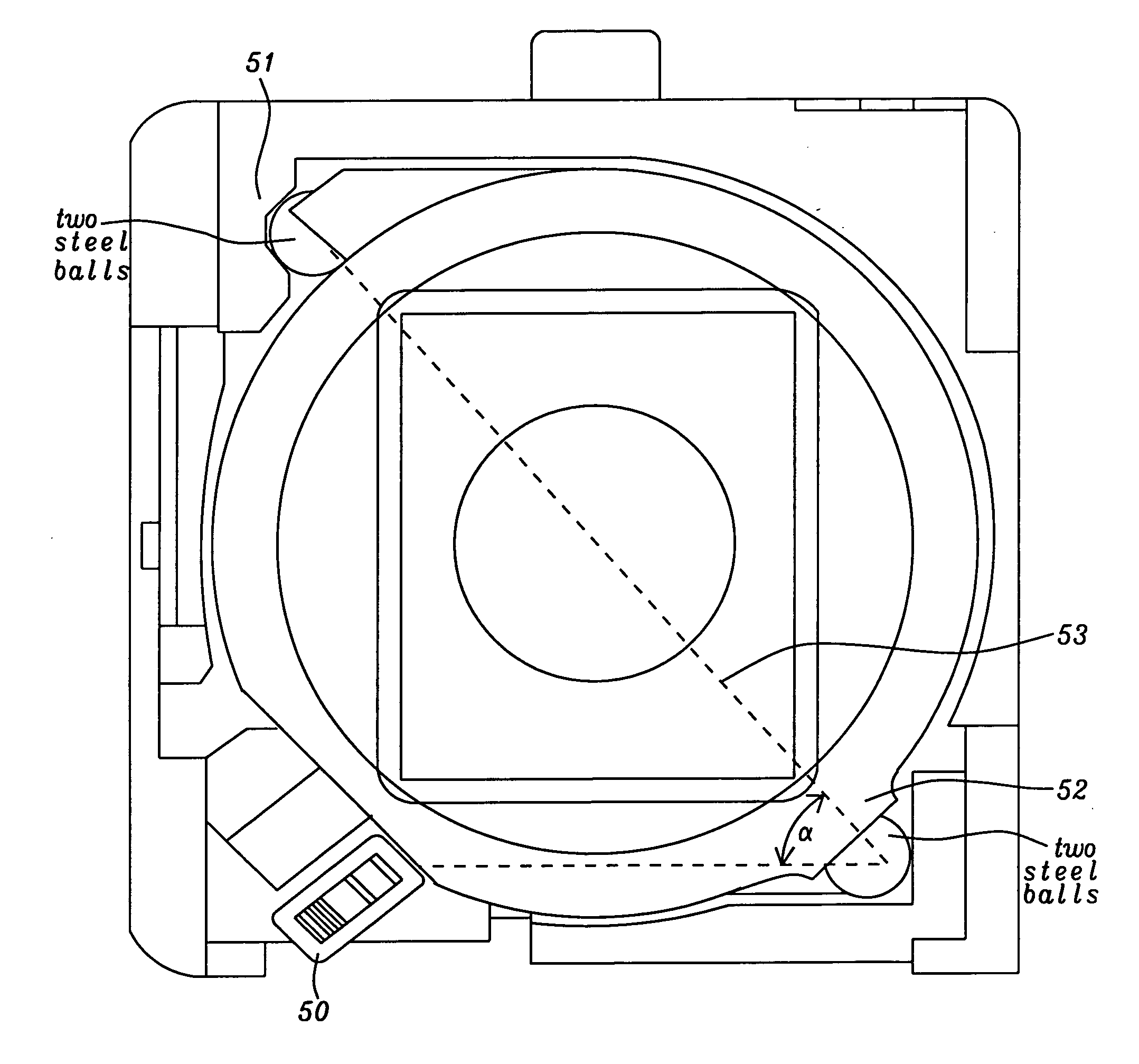
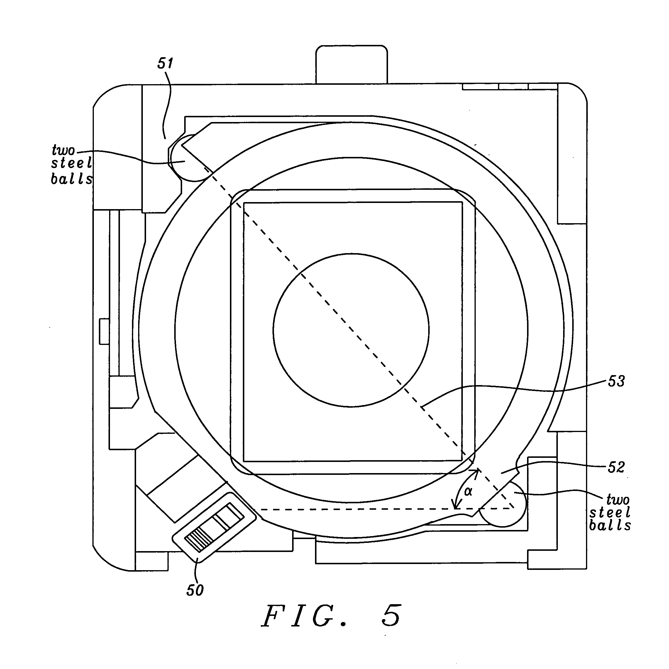
[0035]Preferred embodiments of methods and systems to reduce manufacturing and assembly costs for measures to avoid blocking ball conditions for linear ball bearings using an integrated ball cage are disclosed. Furthermore the invention ensures that balls of the linear ball bearing are kept in place in case of a mechanical shock and that movements of the movable part of linear bearing, such as e.g. a lens barrel of a camera module, can be performed with minimal friction. The present invention could also be used for other applications where ball bearing with just one rotational plane can be used.

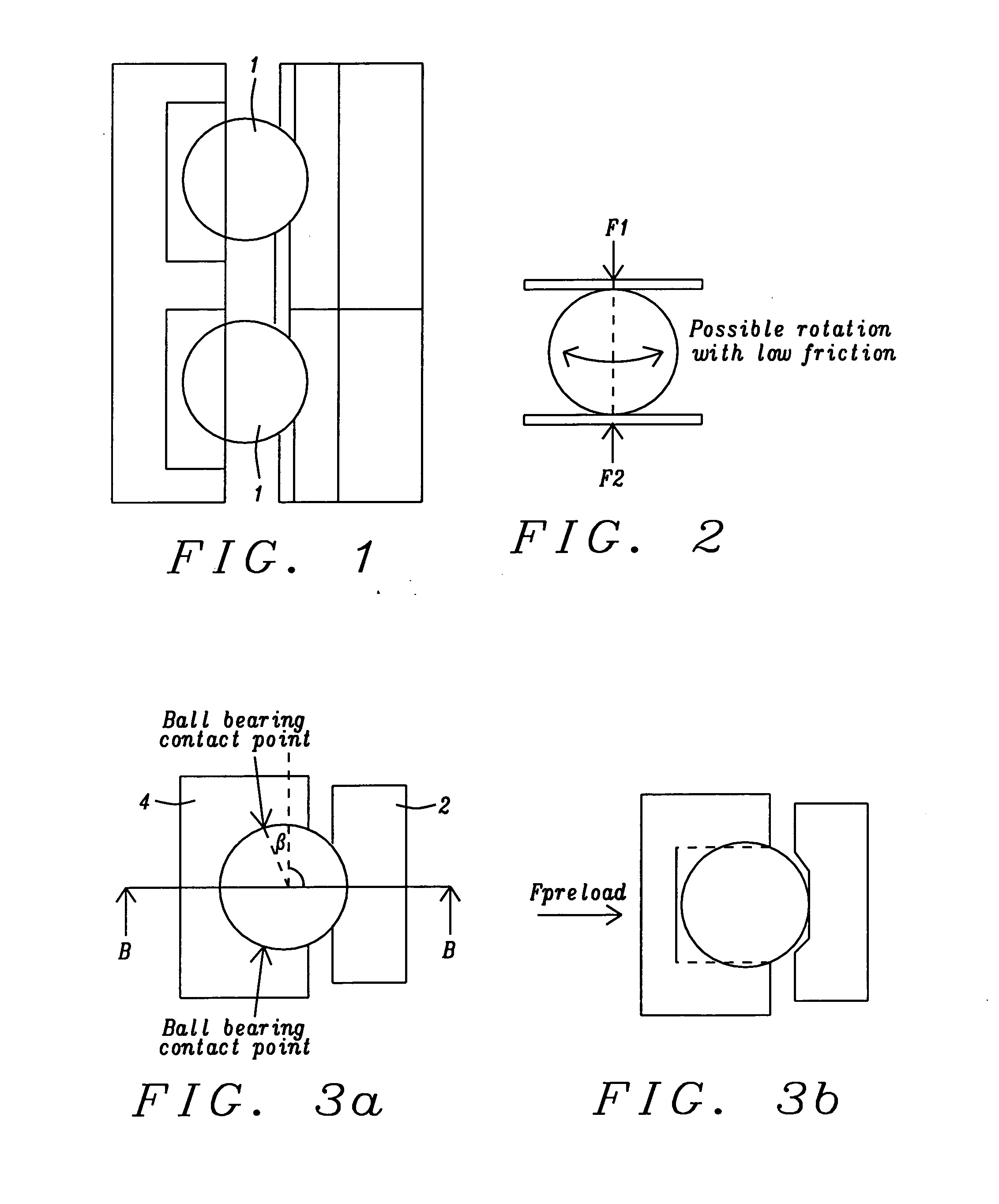
[0036]A preferred embodiment of the invention comprises a linear bearing of a lens barrel using an integrated ball cage. The invention can be applied to other applications requiring small and precise movements. FIG. 2 illustrates an example of a principle of a ball fixture that is used by the invention in an innovative modified way.

[0037]The ball of FIG. 2 is fixed at the two poles F1 and F2 ...


PUM


Abstract

Systems and methods to reduce manufacturing and assembly costs for measures to avoid blocking or creeping ball conditions for linear ball bearings are disclosed. In preferred embodiments two linear ball bearings, a fixed ball bearing and a non-locating ball bearing, are applied to guide movements of a lens barrel of camera modules. Ball cages, which are integrated either in a moving part or in a fixed part of an actuator, are lowering manufacturing and assembly costs. A constant magnetic preload force is applied to both ball bearings to keep the bearings together in case of a mechanic shock. Ball bearing contact points of the fixed ball bearing are shifted asymmetrically by a small angle to withstand horizontal preload forces.

Description

RELATED APPLICATIONS[0001]This application is related to the following US patent applications:[0002]DI09-003 / 004, titled “Camera Module having a low-friction movable lens”, Ser. No. 12 / 661,752, filing date Mar. 23, 2010,[0003]DI10-001, titled “Camera Shutter System”, Ser. No. ______, filing date ______, and[0004]DI10-005, Ser. No. 12 / 806,322 titled “Single actuator configuration for a camera module”, serial number, filing date Aug. 10, 2010,[0005]and the above applications are herein incorporated by reference in their entirety.BACKGROUND OF THE INVENTION[0006](1) Field of the Invention[0007]This invention relates generally to a ball bearing actuator system for camera modules and relates more specifically to integrated ball cages for linear ball bearings used.[0008](2) Description of the Prior Art[0009]For a linear ball bearing system it is important to ensure that each individual ball can roll under all conditions and is not blocked. If a ball is blocked at the end of a ball cavity,...

Claims


Application Information

Patent Timeline
IPC IPC(8): F16C29/04
CPCF16C29/046G02B7/08G03B2205/0053G03B5/00G03B3/00
Inventor UTZ, HUBERT
Owner RPX CORP
Why Eureka
Try Eureka