Image forming apparatus and image density control method

Inactive Publication Date: 2012-09-20
RICOH KK
View PDF4 Cites 15 Cited by
  • Summary
  • Abstract
  • Description
  • Claims
  • Application Information

AI Technical Summary

Benefits of technology

[0012]In one aspect of this disclosure, there is provided an image forming apparatus to form a toner image onto a recoding medium, including an image carrier, an intermediate transfer member, a primary transfer member, a light source, a detector, and a processor. The image carrier bears the toner image and a density adjustment pattern for adjusting image density of the toner image. The intermediate transfer member on which the toner image and the density adjustment pattern are formed, has a first portion and a second portion, and the second portion has a higher glossiness than that of the first portion. The primary transfer member transfers the toner image and the density adjustment pattern from the image carrier onto the intermediate transfer member. The light source emits light onto the intermediate transfer member and the density adjustment pattern formed on the intermediate transfer member. The detector detects intensity of reflected light emitted from the light source and then reflected from the intermediate transfer member and the density adjustment pattern formed on the intermediate transfer member. The processor includes a light-emission intensity adjuster and an image forming condition controller. The light-emission intensity adjuster adjusts light-emission intensity of light emitted from the light source based on detected intensity of light reflected from the second portion of the intermediate transfer member. The image forming condition controller controls image forming conditions for forming the toner image based on the detected intensity of the

Problems solved by technology

However, the surface of the intermediate transfer member may not be very glossy due to limitations placed on the type of material that can be used for the intermediate transfer member by the need to transfer the image carried on the intermediate transfer member onto a transfer sheet.
Moreover, the glossiness of the surface of the intermediate transfer member may decline as the surface of the intermediate transfer member deteriorates over time.
In such cases, the readings from the reflection-type density sensor may become insufficient to adjust correctly the intensity of the light directed onto the image density adjustment pattern.
However,

Method used


Image

  • Image forming apparatus and image density control method
  • Image forming apparatus and image density control method
  • Image forming apparatus and image density control method

Examples


Embodiment Construction

[0022]In describing preferred embodiments illustrated in the drawings, specific terminology is employed for the sake of clarity. However, the disclosure of this patent specification is not intended to be limited to the specific terminology so selected, and it is to be understood that each specific element includes all technical equivalents that operate in a similar manner and achieve a similar result. Referring now to the drawings, wherein like reference numerals designate identical or corresponding parts throughout the several views thereof, and particularly to FIGS. 1 through 6, an electrophotographic image forming apparatus according to illustrative embodiments of the present disclosure is described.

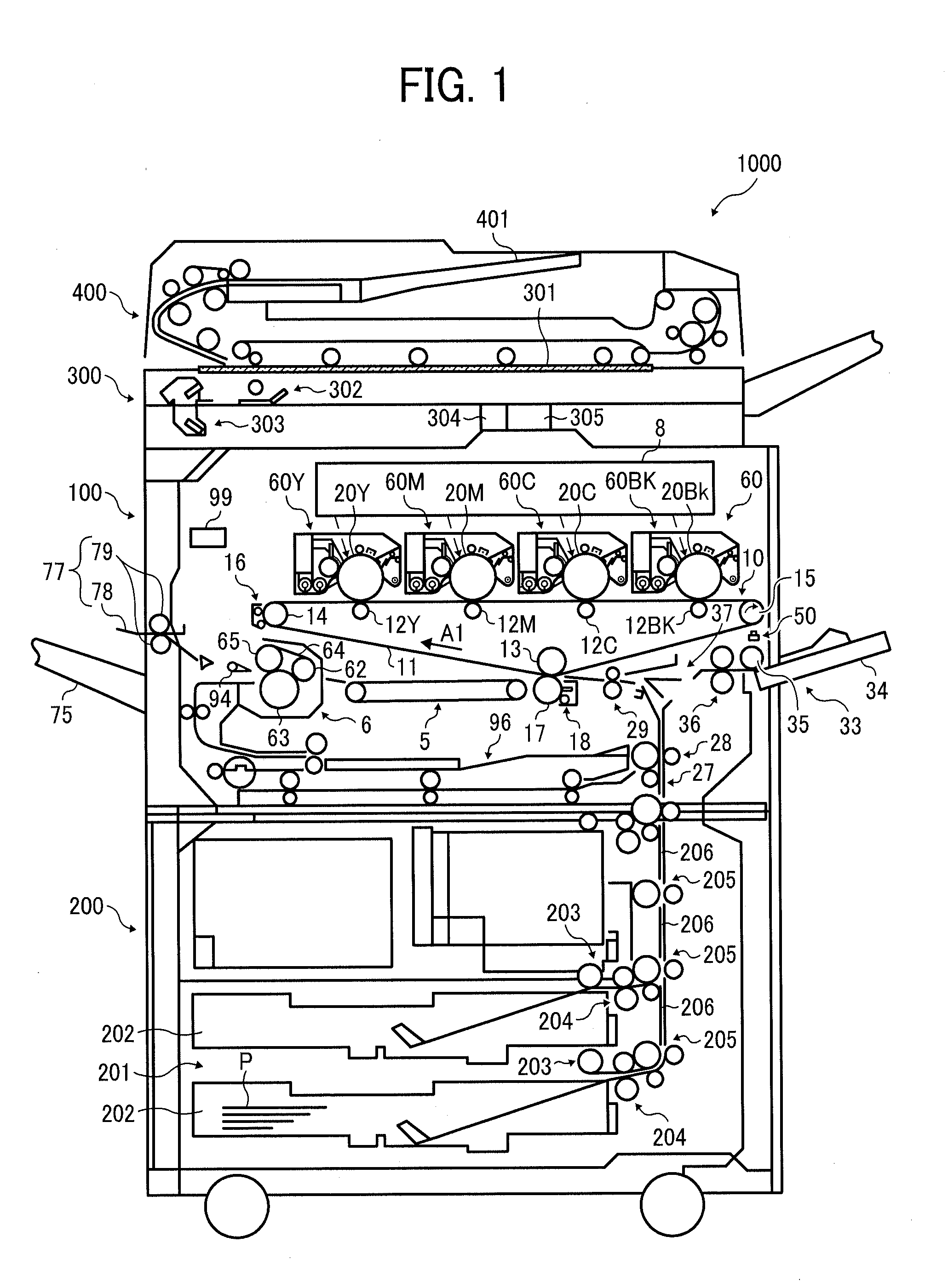
[0023]FIG. 1 is a schematic diagram illustrating a tandem-type color copier as an example of the image forming apparatus 1000 according to an aspect of this disclosure. It is to be noted that the configuration of the present specification is not limited to that shown in FIG. 1. For ex...


PUM


Abstract

An image forming apparatus including an image carrier; an intermediate transfer member having a first portion and a second portion that has a higher glossiness than that of the first portion; a primary transfer member; a light source to emit light to the intermediate transfer member side; a detector to detect intensity of reflected light emitted from the light source and then reflected from the intermediate transfer member and a density adjustment pattern formed on the intermediate transfer member; a processor including a light-emission intensity adjuster to adjust light-emission intensity from the light source based on detected intensity of light reflected from the second portion of the intermediate transfer member; and an image forming condition controller to control image forming conditions for forming a toner image based on the detected intensity of the light reflected from the density adjustment pattern formed on the intermediate transfer member.

Description

CROSS-REFERENCE TO RELATED APPLICATION[0001]This patent application is based on and claims priority pursuant to 35 U.S.C. §119 to Japanese Patent Application No. 2011-058344, filed on Mar. 16, 2011 in the Japan Patent Office, the entire disclosure of which is hereby incorporated by reference herein.BACKGROUND OF THE INVENTION[0002]1. Technical Field[0003]Exemplary aspects of this disclosure generally relate to an image forming apparatus and image density control method, the image forming apparatus, such as a copier, a printer, a facsimile machine, a plotter, or a multifunction machine capable of at least two of these functions, to detect an image on an intermediate transfer member and control density of the forming image.[0004]2. Description of the Related Art[0005]In image forming apparatuses, such as a copier, a printer, a facsimile machine, a plotter, or a multifunction machine capable of at least two of these functions, the density of formed images may fluctuate due to such fact...

Claims


Application Information

Patent Timeline
IPC IPC(8): G03G15/00G03G13/00
CPCG03G2215/0129G03G15/0131G03G2215/00059G03G15/162G03G15/5058G03G15/5054
Inventor KATO, YUJIKATO, TSUTOMUWATANABE, YOHHEI
Owner RICOH KK
Why Eureka
Try Eureka