Limited slippery differential for remote control model vehicle

a remote control model and differential technology, applied in mechanical devices, transportation and packaging, gearing, etc., can solve the problems of power loss, ineffective transfer of engine power to the wheels, etc., and achieve the effect of reducing the speed of the vehicle wheels

Inactive Publication Date: 2012-09-20
TOPWAY MODEL RES
View PDF5 Cites 4 Cited by
  • Summary
  • Abstract
  • Description
  • Claims
  • Application Information

AI Technical Summary

Benefits of technology

[0008]Thus, when the remote control model vehicle is moving over a turn at a high speed, bevel gears of the differential unit are forced into positive engagement with respective transmission gears to reduce the speed of the vehicle wheels that are suspending in the air; when the remote control model vehicle moved over the turn, the bevel gears are forced away from the transmission gears by respective spring members, enabling engine power to be normally transferred to the wheels.

Problems solved by technology

When the model vehicle moved over the turn, the first bevel gears must be disengaged from the respective second bevel gears so that the second bevel gears can return to normal running However, in the aforesaid design, the centrifugal force is insufficient to move the respective first bevel gears completely away from the respective second bevel gears after the model vehicle moved over the turn.
Under this condition, one or a number of the first bevel gears may be still kept in mesh with the respective second bevel gears during rotation of the second bevel gears, thus, the engine power cannot effectively transferred to the wheels, causing power loss.

Method used


Image

  • Limited slippery differential for remote control model vehicle
  • Limited slippery differential for remote control model vehicle
  • Limited slippery differential for remote control model vehicle

Examples


Embodiment Construction

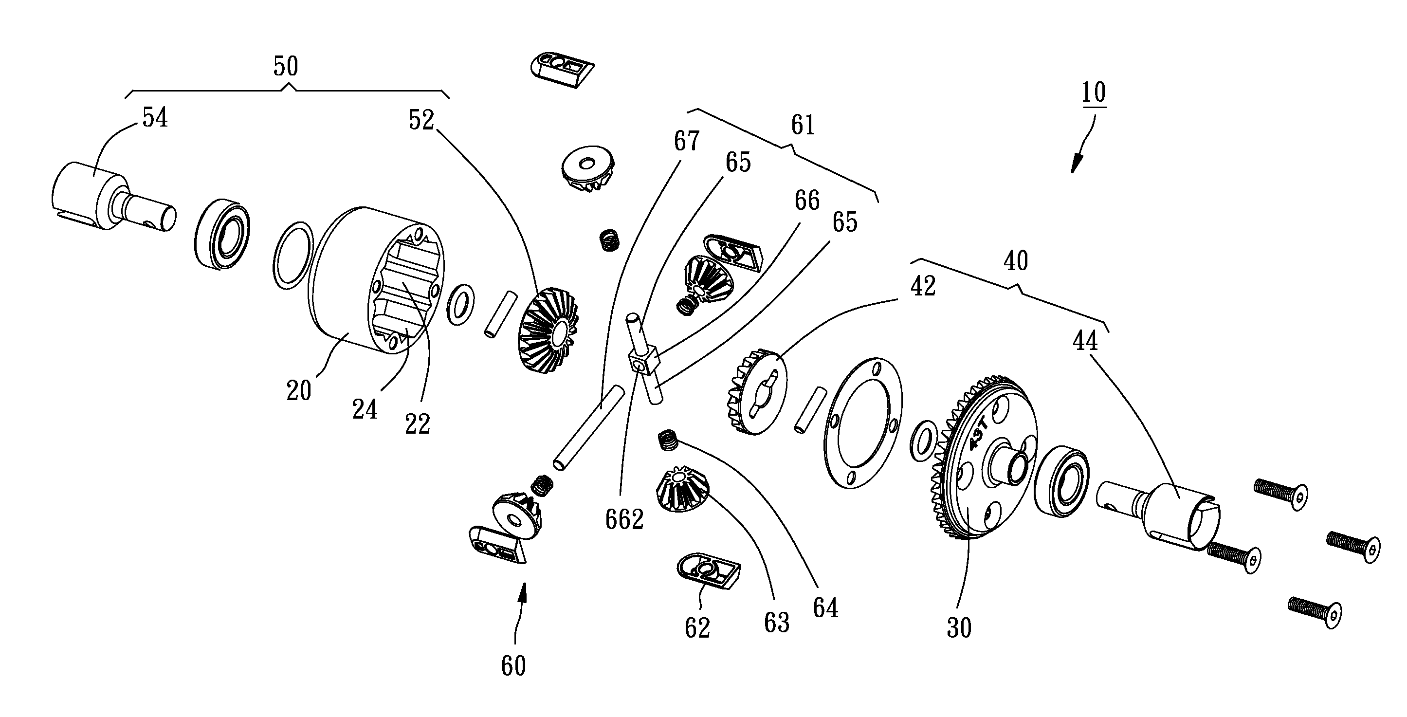
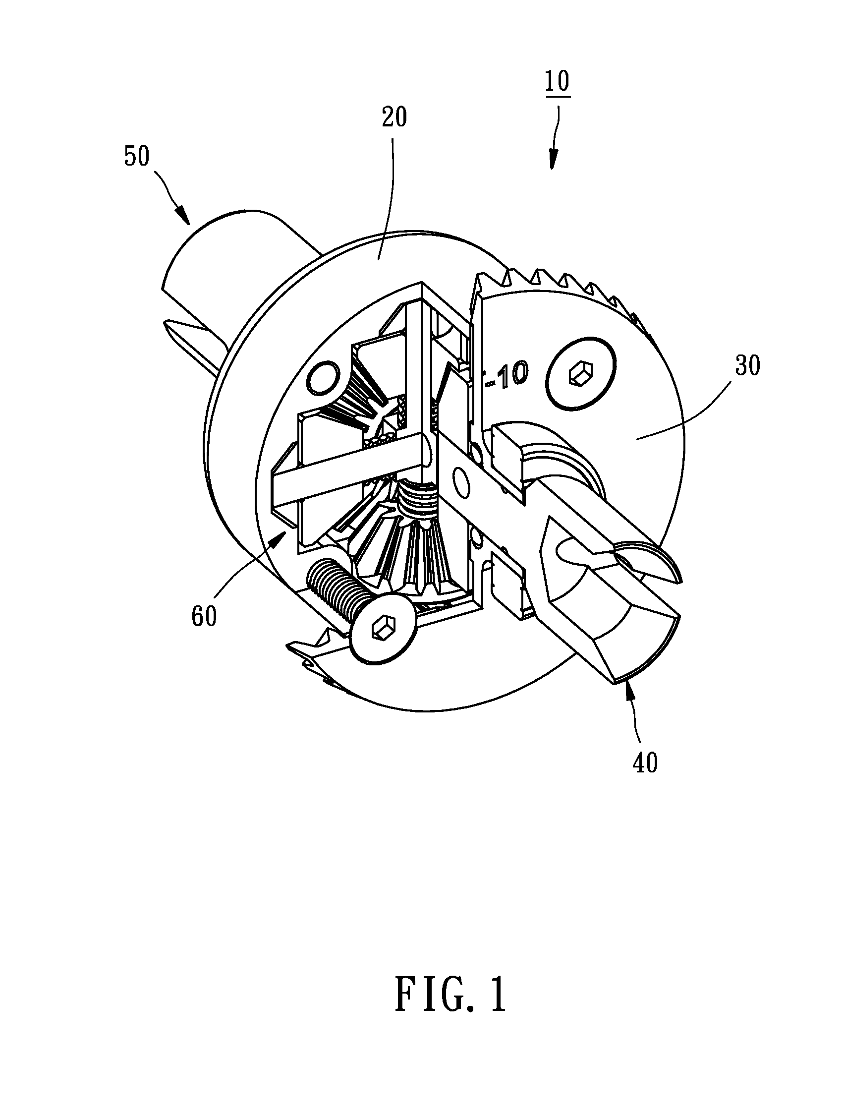
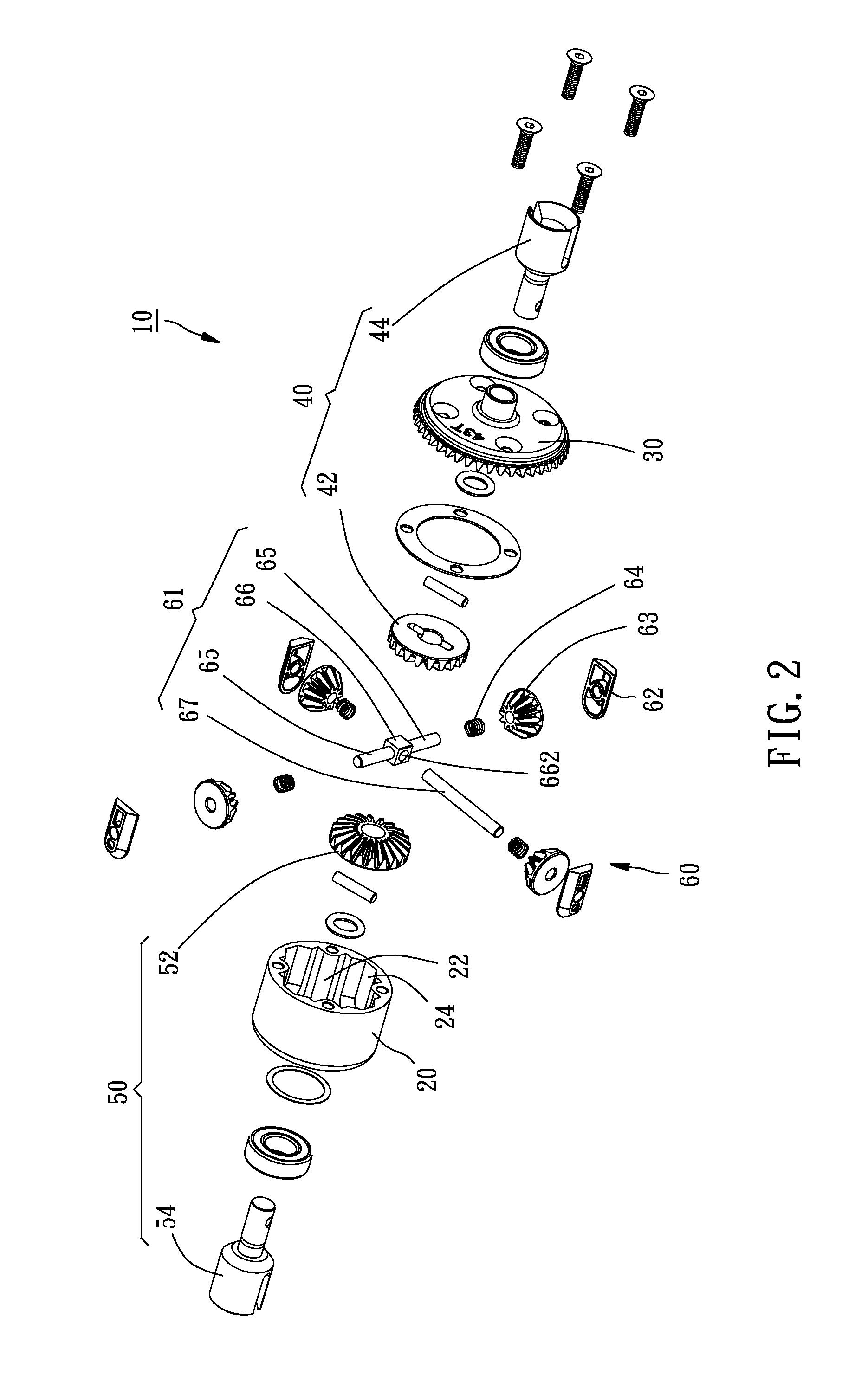
[0016]Referring to FIGS. 1 and 2, a limited slippery differential 10 for remote control model vehicle in accordance with the present invention is shown comprising a housing 20, a main gear 30, a first output unit 40, a second output unit 50 and a differential unit 60.

[0017]The housing 20 defines therein an accommodation chamber 22 and four grooves 24. The grooves 24 are inwardly curved in the peripheral wall of the accommodation chamber 22 in a crossed manner, having a trapezoidal cross section. The distance between one relatively narrower side of each groove 24 and the center of the housing 20 is smaller than the distance between the relative greater opposite side of the respective groove 24 and the center of the housing 20. Further, each groove 24 has one arched end.

[0018]The main gear 30 is mounted on one side of the housing 20 and can be driven by the engine power of a model vehicle to rotate the housing 20.

[0019]Referring to FIG. 3 and FIG. 2 again, the first and second output ...


PUM


Abstract

A limited slippery differential used in a remote control model vehicle is disclosed to include a housing, a main gear mounted on one side of the housing, two transmission gears mounted inside the housing, and a differential unit mounted in the housing. When the remote control model vehicle is moving over a turn at a high speed, bevel gears of the differential unit are forced into positive engagement with respective transmission gears to reduce the speed of the vehicle wheels that are suspending in the air. When the remote control model vehicle moved over the turn, the bevel gears are forced away from the transmission gears by respective spring members, enabling engine power to be normally transferred to the wheels.

Description

BACKGROUND OF THE INVENTION[0001]1. Field of the Invention[0002]The present invention relates to model vehicles and more particularly, to a limited slippery differential for remote control model vehicle.[0003]2. Description of the Related Art[0004]Taiwan Patent Publication No. M336058 discloses a differential design, entitled “Differential for Model Vehicle”. This design uses a cross-shaped shaft to move sliding blocks in respective positioning grooves in a housing when the model vehicle is moving over a turn at a high speed, avoiding impact damage and enabling respective first bevel gears to be moved into engagement with respective second bevel gears to reduce the speed of output shafts and to avoid power loss due to idle running of the wheels that are suspending in the air.[0005]When the model vehicle moved over the turn, the first bevel gears must be disengaged from the respective second bevel gears so that the second bevel gears can return to normal running However, in the afore...

Claims


Application Information

Patent Timeline
Patent Type & Authority Applications(United States)
IPC IPC(8): F16H48/20
CPCF16H2048/282F16H48/28
Inventor YEH, CHUN-MIN
Owner TOPWAY MODEL RES
Why Eureka
Try Eureka