
Medicine feeding apparatus

Inactive Publication Date: 2012-09-20
JVM CO LTD
View PDF8 Cites 25 Cited by
  • Summary
  • Abstract
  • Description
  • Claims
  • Application Information

AI Technical Summary

Benefits of technology

[0016]It is another object of the present invention to provide a medicine feeding apparatus in which medicine products accommodated in a medicine cartridge are kept in fixed positions without a risk of collision therebetween.
[0051]The cover locker may further include an anti-opening structure to prevent opening of the entrance opening of the medicine cartridge even if the key member is used in a state in which the entrance opening of the medicine cartridge faces downward.
[0057]The cartridge locker may further include at least one damping boss protruding from the rear surface of the medicine cartridge to alleviate shock generated when the medicine cartridge is mounted on the cartridge mount, and an elastic damping member provided at the cartridge mount to come into contact with the damping boss when the medicine cartridge is mounted on the cartridge mount.

Problems solved by technology

Especially, ampoules or vials are not equal in shape and automated feeding thereof is difficult.
These ampoules or vials tend to be easily damaged even by low shock because they are made of fragile glass and have a recessed portion between upper and lower ends thereof to allow a user to use medicine received in an ampoule by pressing the recessed portion.
In the case of the pouch type medicine products, pouches become unequal in shape depending on medicine, such as tablets or medicinal powder, received in the pouches and thus, are likely to be damaged upon collision therebetween, which may cause invasion of foreign substances into the pouches or discharge of medicine from the pouches, resulting in damage to medicine.
The PTP type medicine products are generally made of a material to allow the user to easily tear off the cover and tend to be easily damaged even by low shock, thus requiring careful handling in storage or feeding of medicine.

Method used


Image

  • Medicine feeding apparatus
  • Medicine feeding apparatus
  • Medicine feeding apparatus

Examples


first embodiment

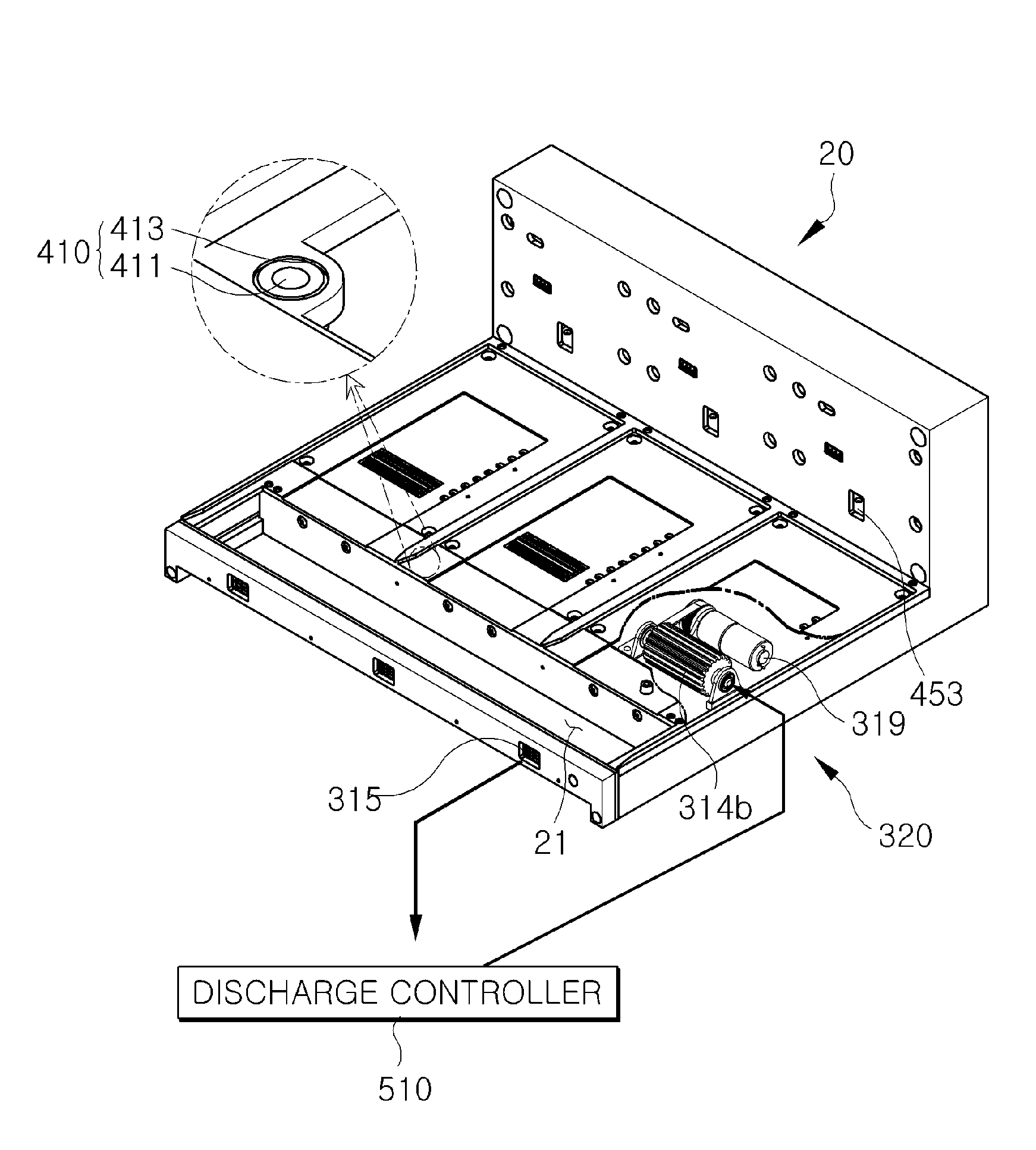
[0122]FIGS. 7A, 7B and 7C are views illustrating operation of the medicine discharge mechanism of the medicine feeding apparatus according to the present invention.

[0123]The above described discharge hole 15, as illustrated in FIG. 7A, has a size greater than the size of the medicine products M accommodated in the medicine cartridge 10, and the discharge member 313 is initially positioned to open the discharge hole 15 by a minimum degree required to discharge the medicine product M.

[0124]More specifically, if the discharge drive unit 321 mounted to the cartridge mount 20 is driven to rotate the pinion member 322b, the discharge member 313 having the rack member 322a engaged with the pinion member 322b is moved, thereby opening the discharge hole 15.

[0125]If the medicine product M is discharged through the open discharge hole 15, the discharge sensor 315 senses the discharged medicine product M and sends the sensed result to the discharge controller 510. The discharge controller 510 ...

second embodiment

[0163]A medicine discharge mechanism 330 as illustrated, allows the medicine products M to be accommodated respectively in independent spaces. To this end, the medicine discharge mechanism 330 includes front and rear rotating shafts 331 installed to connect opposite lateral surfaces of the cartridge body 11 to each other, and a partitioned conveyor belt 333 rotatably engaged with the front and rear rotating shafts 331 to connect the front and rear rotating shafts 331 to each other.

[0164]Here, the front rotating shaft 331 located toward the front surface of the cartridge body 11 is preferably located above the discharge hole 15. This allows medicine products seated on the partitioned conveyor belt 333 to fall through the discharge hole 15 as the partitioned conveyor belt 333 is turned downward when being rotated around the rotating shaft 331 located near the discharge hole 15.

[0165]The partitioned conveyor belt 333 is configured such that the medicine products M are seated on an upp...

fourth embodiment

[0237]Here, the discharge driving unit and the discharge driving gear have the same configuration as those of the above described fourth embodiment and thus, a detailed description thereof will be omitted.

[0238]If the medicine cartridge 10 is mounted on the cartridge mount 20 and the discharge drive unit is driven to discharge the medicine products, the discharge driving gear is rotated by the discharge drive unit and simultaneously, the discharge driven gear 392 engaged with the discharge driving gear is rotated, causing the rotation drive shaft member 393 connected to the discharge driven gear 392 to be rotated. As the rotation drive shaft member 393 is rotated, the discharge roller member 391 connected to the discharge drive belt 394 is rotated.

[0239]In this case, the discharge roller member 391 is rotated and moved downward, thereby acting to push the medicine product P toward the discharge hole 15 while coming into contact with one surface of the medicine product P. As such, th...


PUM


Abstract

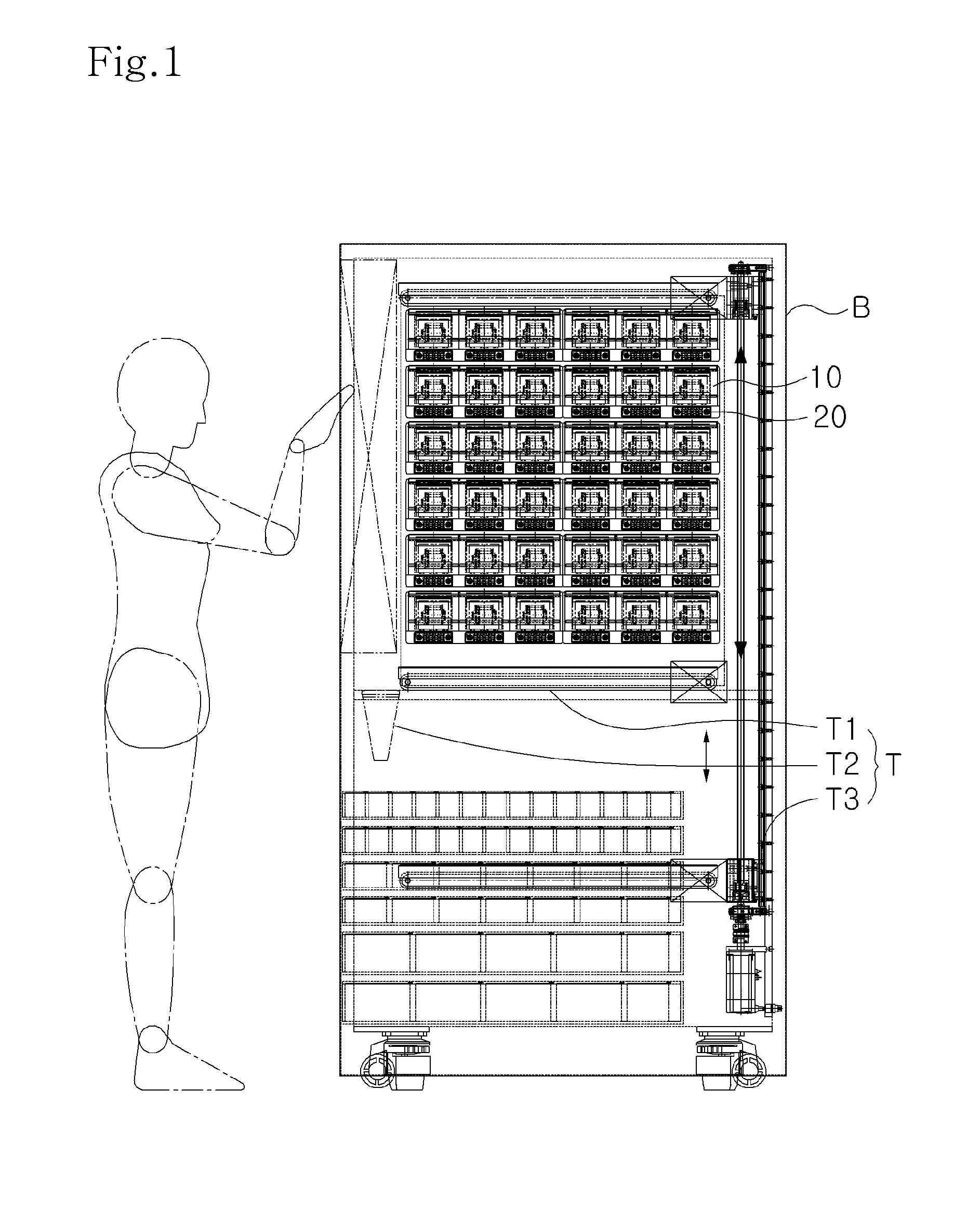
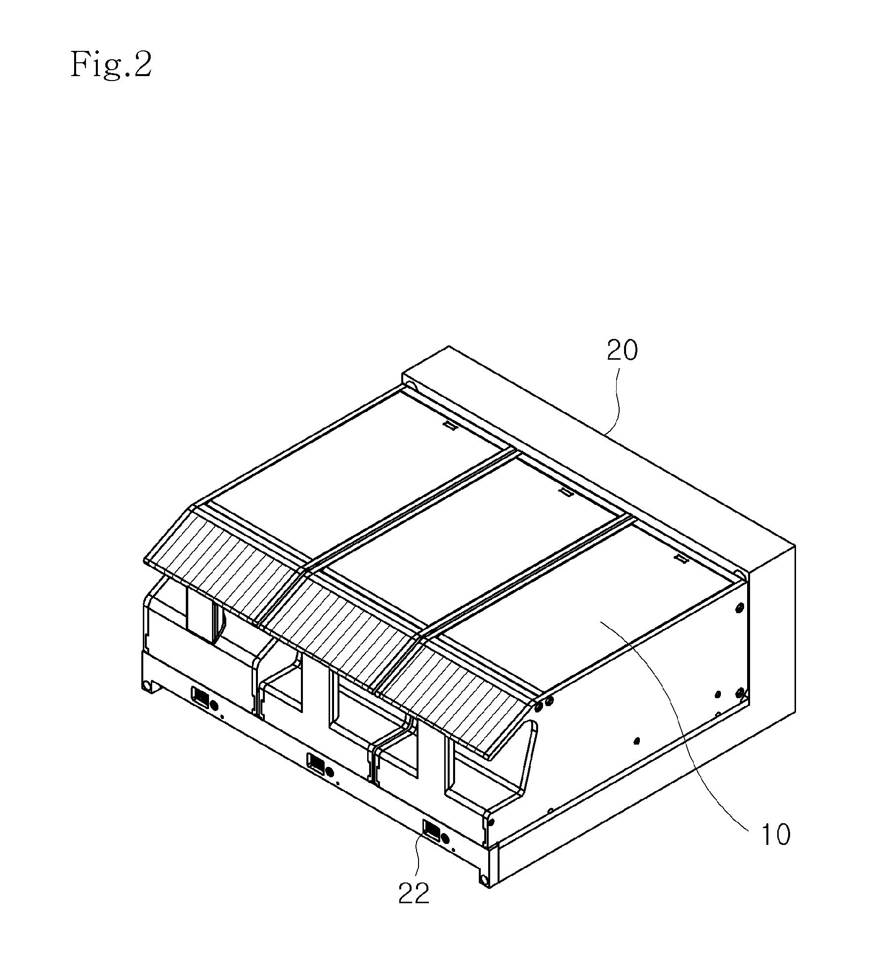
Disclosed is a medicine feeding apparatus. The medicine feeding apparatus includes a medicine cartridge, a cartridge mount, a medicine discharge mechanism, and a discharge drive mechanism. The medicine cartridge has an entrance opening formed in the top thereof, through which a medicine product is put into the medicine cartridge, and a discharge hole formed in a front position of the bottom thereof, through which the medicine product is discharged from the medicine cartridge by operation of the medicine discharge mechanism. The entrance opening is provided with a cover. The medicine cartridge is mounted on an upper surface of the cartridge mount, and the cartridge mount has an outer discharge hole communicating with the discharge hole to discharge the medicine product from the cartridge mount. The discharge drive mechanism is provided at the medicine cartridge and the cartridge mount and serves to drive the medicine discharge mechanism.

Description

BACKGROUND OF THE INVENTION[0001]1. Field of the Invention[0002]The present invention relates to a medicine feeding apparatus, and more particularly, to a medicine feeding apparatus, which can prevent medicine from being damaged in the course of being dispensed in the case where medicine products are not equal in shape or are fragile.[0003]2. Description of the Related Art[0004]Generally, there are various kinds and shapes of medicine products.[0005]Especially, ampoules or vials are not equal in shape and automated feeding thereof is difficult. These ampoules or vials tend to be easily damaged even by low shock because they are made of fragile glass and have a recessed portion between upper and lower ends thereof to allow a user to use medicine received in an ampoule by pressing the recessed portion.[0006]There are also pouch type medicine products in which medicine is put into a paper or vinyl pouch having an open end and the open end of the pouch is sealed before the medicine prod...

Claims


Application Information

Patent Timeline
IPC IPC(8): G06F17/00B65D83/04
CPCG07F11/005G07F11/26G07F17/0092G07F11/62G07F11/44
Inventor KIM, JUN-HO
Owner JVM CO LTD
Learn More