

Portable deck
a technology of portability and decking, applied in the field of portability decking, can solve the problem of impossibility of losing hardware, etc., and achieve the effects of increasing the ease of handling and assembly, facilitating use, and being easy to handl
- Summary
- Abstract
- Description
- Claims
- Application Information
AI Technical Summary
Benefits of technology
Problems solved by technology
Method used
Image

Examples
Embodiment Construction
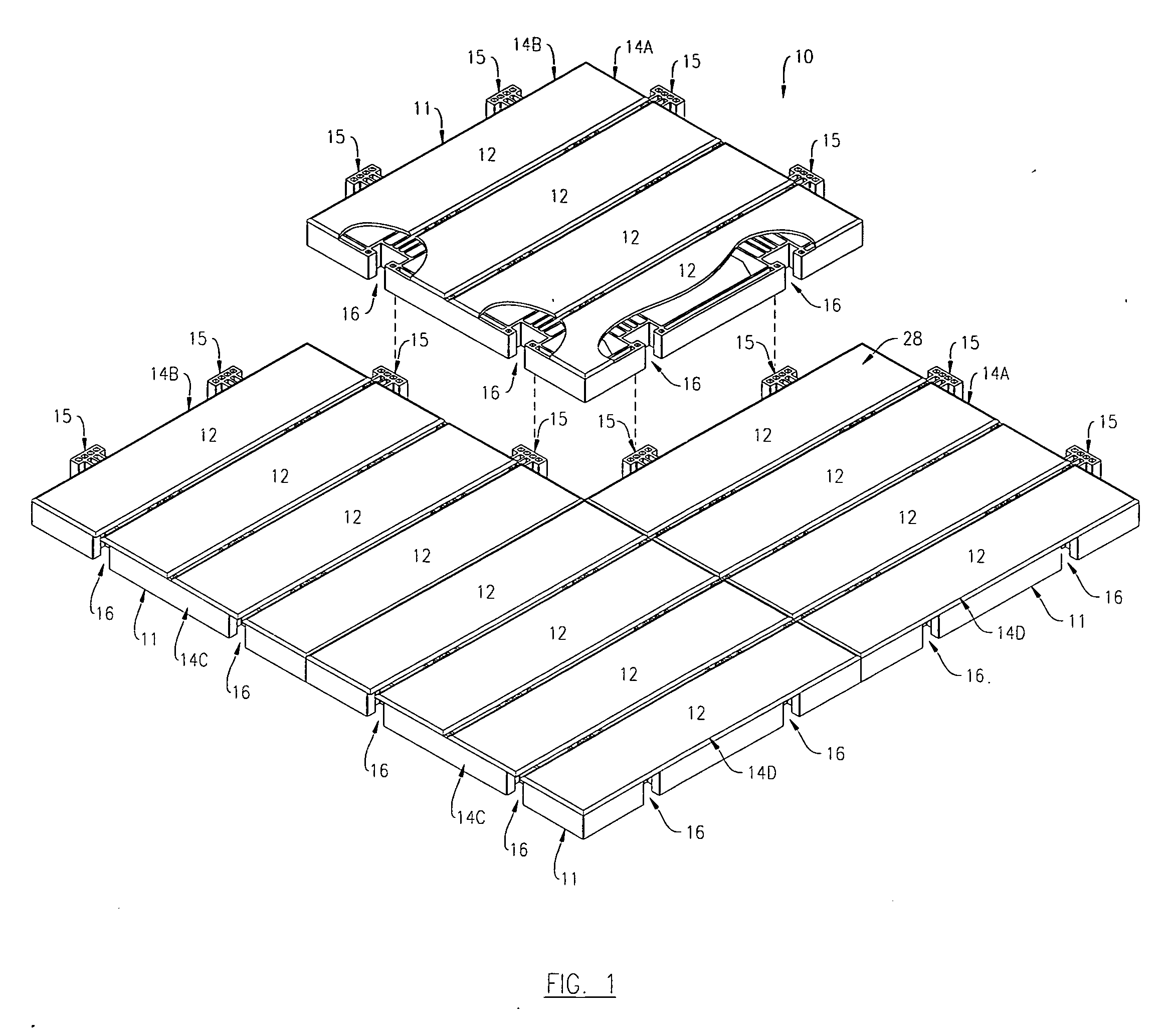
[0020]FIG. 1 is a top view of a four module section of the disclosed invention, showing a top view of one embodiment 10 of the disclosed portable deck. FIG. 1 portrays the assembly process forming the rows. For purposes of illustration only, FIG. 1 shows a portable deck made up of four modules 11, although the portable deck might be made up of any number of modules 11. Each module 11 is made up of panels 12. Each panel 12 has a top surface 28. There are four sides; first side 14A is attached to one end of the panels 12, and third side 14C is attached to another end of the panels 12. The second side 14B and fourth side 14D are opposite each other and adjacent to sides 14A and 14C. First Side 14A has two male connectors 15. Second side 14B has two male connectors 15. Third Side 14C has two female connectors 16 as shown. Fourth side 14D also has two female connectors 16. The male connectors 15 and female connectors 16 are shown directly across from each other.
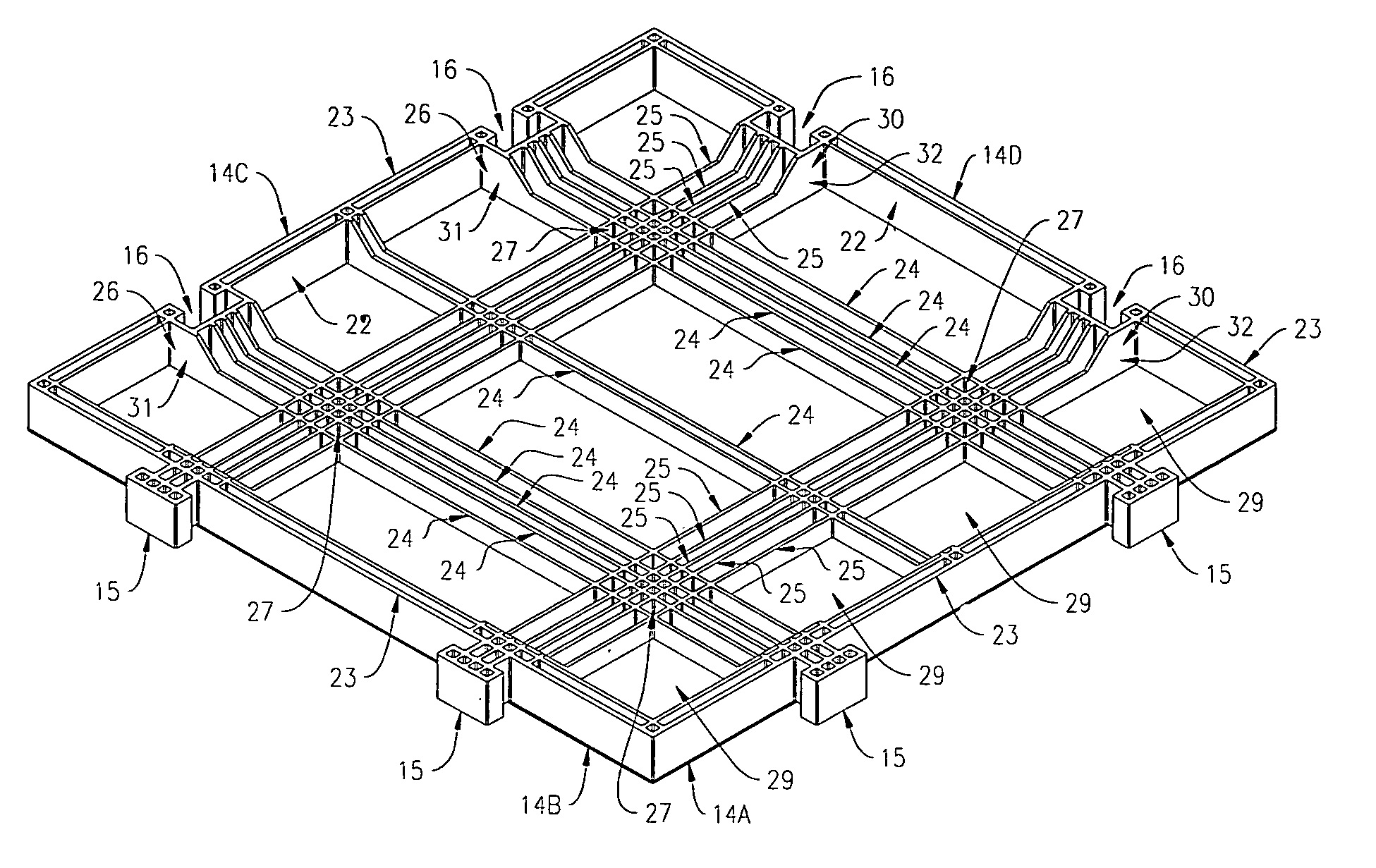
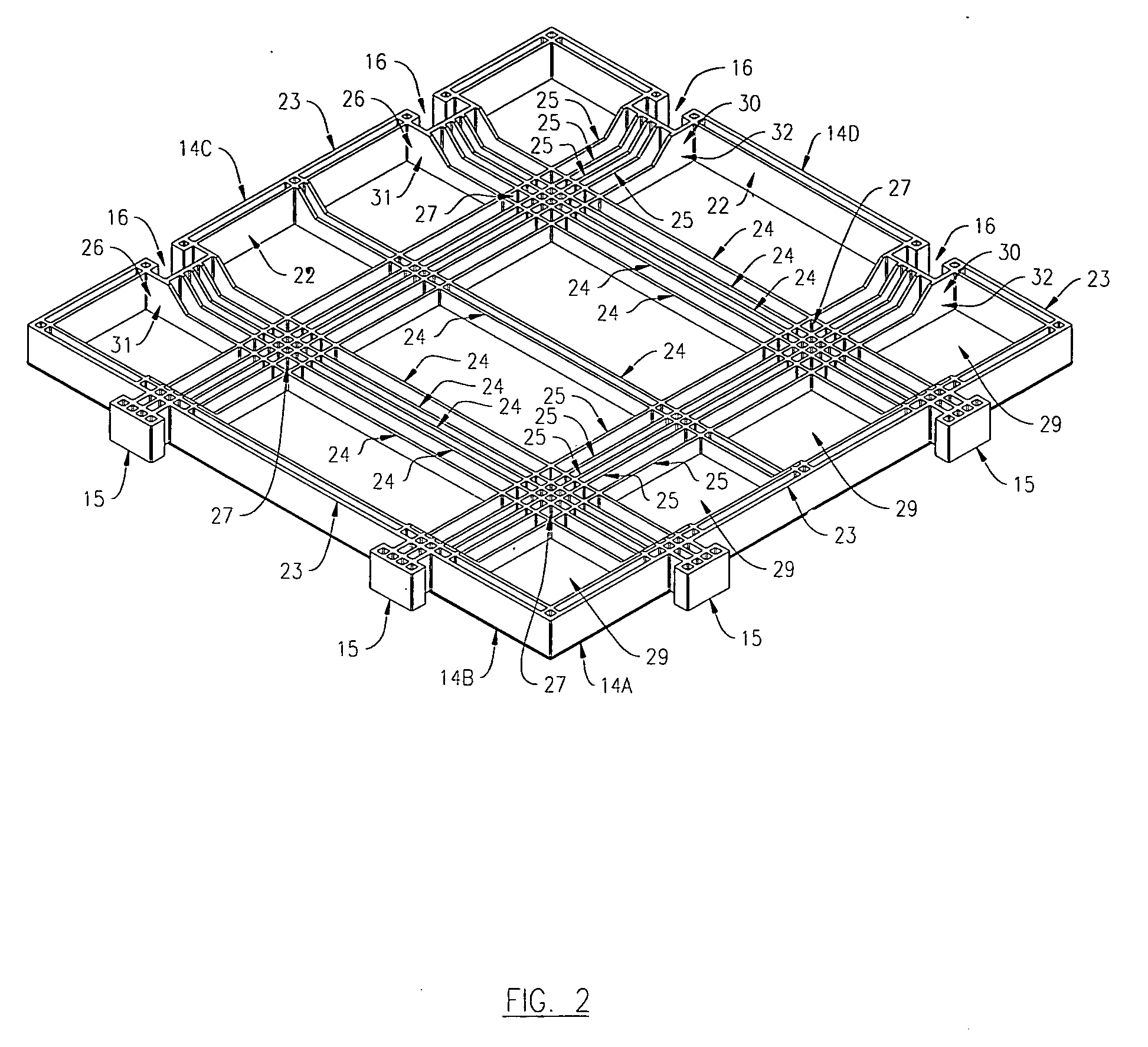
[0021]FIG. 2 shows a pers...
PUM
| Property | Measurement | Unit |
|---|---|---|
| length | aaaaa | aaaaa |
| length | aaaaa | aaaaa |
| length | aaaaa | aaaaa |
Abstract
Description
Claims
Application Information