Weather strip and production method thereof

a weather strip and production method technology, applied in the field of weather strips, can solve the problems of reducing the productivity or increasing the cost, reducing the width dimension, and increasing the load in the vicinity of the connecting portion, so as to prevent the deterioration of the sealing capability, reduce the quality of the appearance of the weather strip or the sealing capability, and improve the appearance quality

Inactive Publication Date: 2012-09-27
TOYODA GOSEI CO LTD
View PDF24 Cites 22 Cited by
  • Summary
  • Abstract
  • Description
  • Claims
  • Application Information

AI Technical Summary

Benefits of technology

[0014]The present invention is made to solve the above-described problems, and an object of the present invention is to provide a weather strip having a good quality of appearance and preventing a sealing capability from being deteriorated. In addition, another object of the present invention is to provide a method of producing a weather strip which can withdrawn a core mold from a relatively narrow width in a region of an injection molded portion, when the weather strip having an extrusion molded portion connected to the injection molded portion is produced, without causing a decrease in the quality of the appearance of the weather strip or a sealing capability thereof.

Problems solved by technology

Therefore, there may be a problem in that if the front end of the core body is formed in a taper shape in view of ease of insertion, an insertion margin and a width of the injection molded portion are widened thereby lowering the productivity or increasing the cost.
Such a configuration can reduce the width dimension of a connecting portion, but since the hollow portion is clogged in the connecting portion, a load may be locally increased in the vicinity of the connecting portion when the opening / closing member is closed.
Further, since a groove of the trim portion or the like is clogged, a process of cutting the sheet material after the bonding process is inevitable.
Therefore, a problem such as a decrease in productivity or an increase in cost may occur.
In addition, a stepped portion is likely to form between the extrusion molded portion and the connecting portion, and there is a fear of a reduction of sealing capability.
However, in the weather strip disclosed in JP-A-7-164978, since the width (connecting width) of the injection molded portion in the longitudinal direction of the weather strip is relatively long, and the opening, which is used as an air discharging hole, as well as the core withdrawing hole, formed in the injection molded portion has a relatively large opening area, there is a concern that it may look unattractive, and the quality of the appearance is deteriorated.
In addition, since the large opening is formed in the injection molded portion, there is a concern that a load difference may be increased between the injection molded portion and the extrusion molded portion in the vicinity of the injection molded portion when the opening / closing member is closed, the sealing capability is deteriorated.
If such a support lip is provided, it may be difficult to carry out the core withdrawing operation.
Therefore, since the working of withdrawing the core body depends only on the deformation of the sealing wall side of the hollow sealing portion, it is difficult to carry out the core withdrawing operation.

Method used


Image

  • Weather strip and production method thereof
  • Weather strip and production method thereof
  • Weather strip and production method thereof

Examples


first embodiment

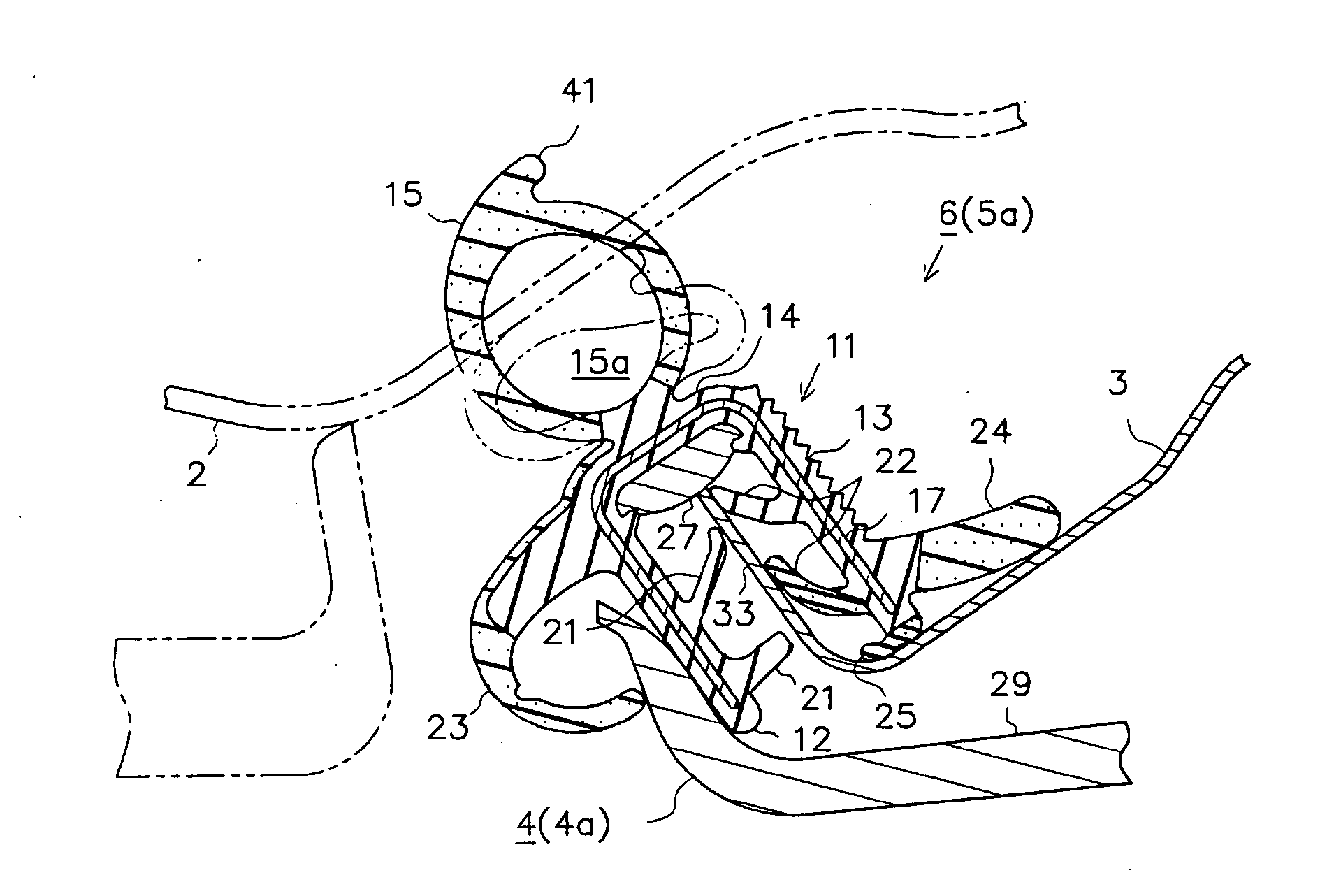
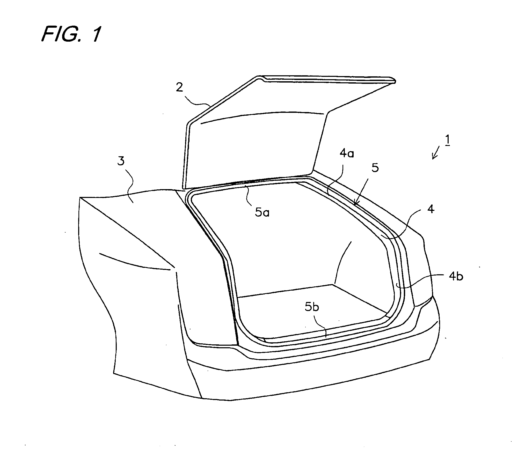
[0102]A first embodiment will now be described with reference to the accompanying drawings. As shown in FIG. 1, an automobile 1 serving as an automobile vehicle is provided with a luggage compartment door 2 serving as an opening / closing member for opening and closing an opening 4 of a luggage compartment which is formed in a body 3 serving as an automobile body. In addition, a circumferential edge of the opening 4 is provided with a weather strip 5 for sealing a gap between the luggage compartment door 2 and a circumferential edge of the opening 4 when the luggage compartment door 2 is closed.

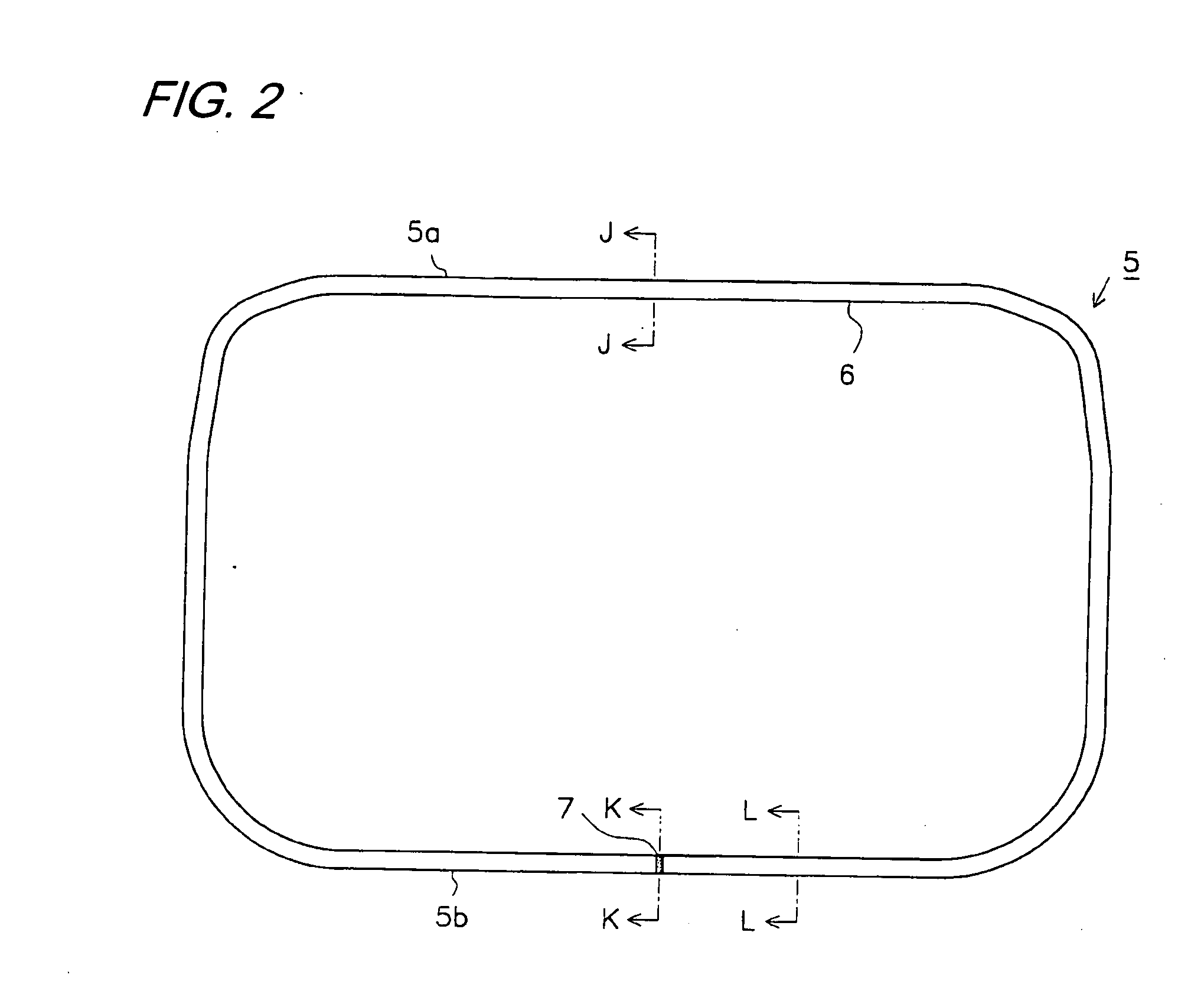
[0103]As shown in FIG. 2, the weather strip 5 according to the first embodiment includes an extrusion molded portion 6 formed in the shape of a substantially straight line by injection molding, and an injection molded portion 7 (portion indicated by a scatter plot shape in FIGS. 2 and 5) for connecting both ends of the extrusion molded portions 6 in the shape of a straight line, and is formed i...

second embodiment

[0152]A second embodiment will now be described with reference to the accompanying drawings. FIG. 12 is a perspective view illustrating an automobile in a state in which a front door is opened. FIG. 13 is a front view of a weather strip. FIG. 14 is a cross-sectional view taken along the line J-J in FIG. 13 illustrating a weather strip.

[0153]As shown in FIG. 12, an automobile 101 serving as an automobile vehicle is provided with an automobile door (front door in the drawing; referred to as a “door 102”) which can be opened or closed. In addition, a circumferential edge of a door opening 4 of an automobile body 103 (automobile body) corresponding to the door 102 is provided with an opening trim weather strip 105 (referred to as a “weather strip 105”).

[0154]As shown in FIG. 13, the weather strip 105 according to the second embodiment includes an extrusion molded portion 106 formed in the shape of a substantially straight line by injection molding, and an injection molded portion 107 (p...

third embodiment

[0208]A third embodiment will now be described with reference to the accompanying drawings. FIG. 22 is a perspective view illustrating a loop panel or the like of an automobile. FIG. 23 is a front view of a weather strip. FIG. 24 is a cross-sectional view taken along the line J-J in FIG. 23 illustrating a weather strip.

[0209]As shown in FIG. 22, a loop panel 201 of an automobile vehicle is provided with a loop panel opening 202 and a sliding loop 203 serving as a movable loop for opening and closing the loop panel opening 202. A circumferential edge of the sliding loop 203 is provided with a sliding loop weather strip 205 (referred to as a “weather strip 205”).

[0210]As shown in FIG. 23, the weather strip 205 according to the third embodiment includes an extrusion molded portion 206 formed in the shape of a substantially straight line by injection molding, and an injection molded portion 207 (portion indicated by a scatter plot shape in FIGS. 23 and 26) for connecting both ends of th...


PUM

PropertyMeasurementUnit
widthaaaaaaaaaa
widthaaaaaaaaaa
circumferential lengthaaaaaaaaaa

Abstract

A weather strip includes an extrusion molded extrusion molded portion, an injection molded portion which connects both ends of the extrusion molded portions in a straight line shape, a trim portion which is mounted on a circumferential edge of an opening of a luggage compartment, and a hollow sealing portion which protrudes from the trim portion. The injection molded portion is formed such that a width thereof is 2.0. The hollow sealing portion is provided with a core withdrawing hole, through which a core mold forming an inner peripheral surface of the hollow sealing portion is withdrawn after formation. The core withdrawing hole is formed such that a length thereof along a circumferential direction of the inner peripheral surface of the hollow sealing portion is 40% of a circumferential length of the inner peripheral surface.

Description

BACKGROUND OF THE INVENTION[0001]1. Field of the Invention[0002]The present invention relates to a weather strip capable of sealing a gap between an opening of an automobile body or the like, and an opening / closing member for opening and closing the opening, and a production method thereof.[0003]2. Related Art[0004]Conventionally, a weather strip is installed at an edge portion of an opening which is formed in a body (automobile body) of an automobile or the like. The weather strip includes a trim portion of a substantially U-shaped cross section serving as a mounting base portion mounted on a flange portion which is provided along the edge portion of the opening, and a hollow sealing portion protruding from the trim portion and having a hollow portion. When an opening / closing member for opening and closing the opening is closed, a gap between the body and the opening / closing member is sealed by the pressing contact between the hollow sealing portion and the edge portion of the open...

Claims


Application Information

Patent Timeline
Patent Type & Authority Applications(United States)
IPC IPC(8): E06B7/22B29C45/00B29C47/00B29C69/02B29C70/00B29C48/12
CPCB29L2031/005B29D99/0053B29K2623/16B29K2223/16B29K2423/16B29C45/14409B29C47/003B29K2023/16B29K2823/16B60J10/0005B60J10/0008B60J10/0031B60J10/0065B60J10/081B60J10/12B29L2031/26B60J10/24B60J10/84B60J10/2335B60J10/16B60J10/17B60J10/32B60J10/82B29C48/12
Inventor MINOURA, HIDEAKITAKAHASHI, KAZUHIROKUBO, YOSHIHISAKAWAI, TATSUYA
Owner TOYODA GOSEI CO LTD
Why Eureka
Try Eureka