Ink fountain liner and blade guard

Inactive Publication Date: 2012-09-27
SANDEN NORTH AMERICA
3 Cites 1 Cited by

AI-Extracted Technical Summary

Problems solved by technology

This can result in the blade edge and the ink roller coming into contact with each other.
This metal on metal contact can be detrimental to the printing process in several ways.
The metal to metal friction can wear down the blade edge at points of contact causing irregularities in the width of the blade edge, which results in a decreased life of the blade.
The friction can also raise the temperature of the ink which affects the viscosity of the ink, and in turn t...

Benefits of technology

[0010]In the practice of the present invention an ink fountain liner is provided for an offset press. Without limitation, the liner is adapted for prolonging the life of an ink fountain blade by preventing irregularities from forming on the blade and by acting as a resurfacing material for a previously damaged blade and controlling the temperature of the ink by eliminating metal to metal friction and reducing cleaning time and cleaning materials. T...

Abstract

The present invention is an ink fountain liner and blade guard adapted for prolonging the life of an ink fountain blade and controlling the temperature of the ink by eliminating metal to metal friction and reducing cleaning time and cleaning materials. The liner covers the bottom surface of an ink fountain and includes a strip of double sided adhesive with a backing strip preserving the side of the adhesive not affixed to the liner. The front edge of the preferred embodiment is connected at a creased line to a flap that covers the ink fountain blade.

Application Domain

Office printingPrinting press parts

Technology Topic

Image

  • Ink fountain liner and blade guard
  • Ink fountain liner and blade guard
  • Ink fountain liner and blade guard

Examples

  • Experimental program(1)

Example

DETAILED DESCRIPTION OF THE DRAWINGS
I. Introduction and Environment
[0021]As required, detailed aspects of the present invention are disclosed herein; however, it is to be understood that the disclosed aspects are merely exemplary of the invention, which may be embodied in various forms. Therefore, specific structural and functional details disclosed herein are not to be interpreted as limiting, but merely as a basis for the claims and as a representative basis for teaching one skilled in the art how to variously employ the present invention in virtually any appropriately detailed structure.
[0022]Certain terminology will be used in the following description for convenience in reference only and will not be limiting. For example, up, down, front, back, right and left refer to the invention as orientated in the view being referred to. The words, “inwardly” and “outwardly” refer to directions toward and away from, respectively, the geometric center of the aspect being described and designated parts thereof. Said terminology will include the words specifically mentioned, derivatives thereof and words of similar meaning.
[0023]Referring to the drawings in more detail, the reference numeral 2 generally designates an ink fountain liner and blade guard embodying an aspect of the present invention. Without limitation on the range of useful applications of the ink fountain liner and blade guard 2 comprising the present invention, an exemplary application is disclosed comprising a panel 4 connected to a front flap 6 at a creased line 8. A double sided adhesive strip 10 is affixed to the bottom surface 7 (FIG. 6) of the panel 4 with a backing strip 12 covering the adhesive layer on the bottom of the strip 10. The adhesive strip 10 can be of any suitable width. Without limitation on the generality of materials that can be used with the present invention, a suitable material for the liner is clear polyester sheeting from Ridout Plastics of San Diego, Calif. Without limitation on the generality of adhesives that can be used with the present invention, a suitable adhesive is Cactus No. Y291M Double-Coated Adhesive Tape from V. Himark (USA) Inc. of Irwindale, Calif.
II. Preferred Embodiment or Aspect of the Ink Fountain Liner and Blade Guard 2
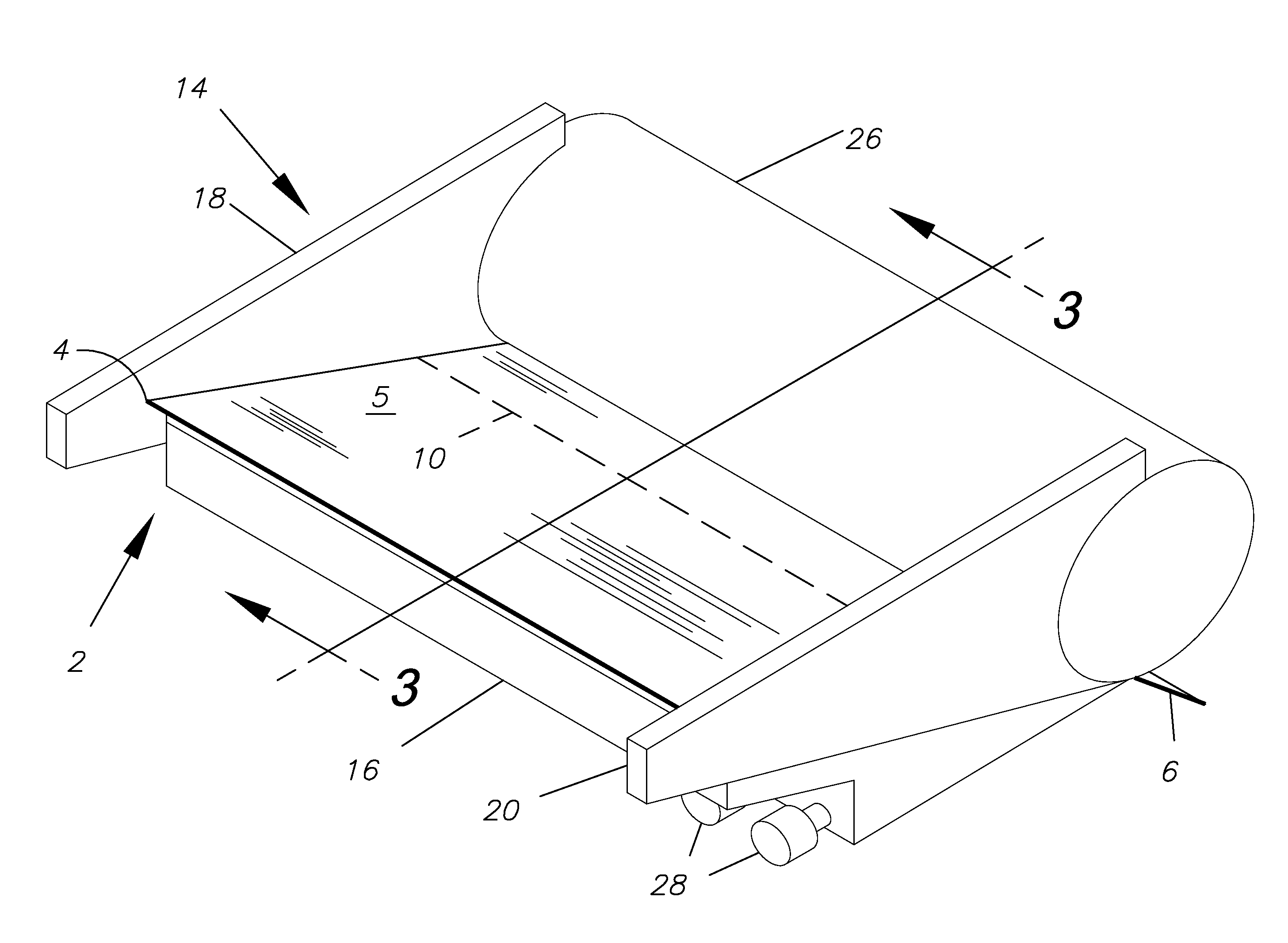
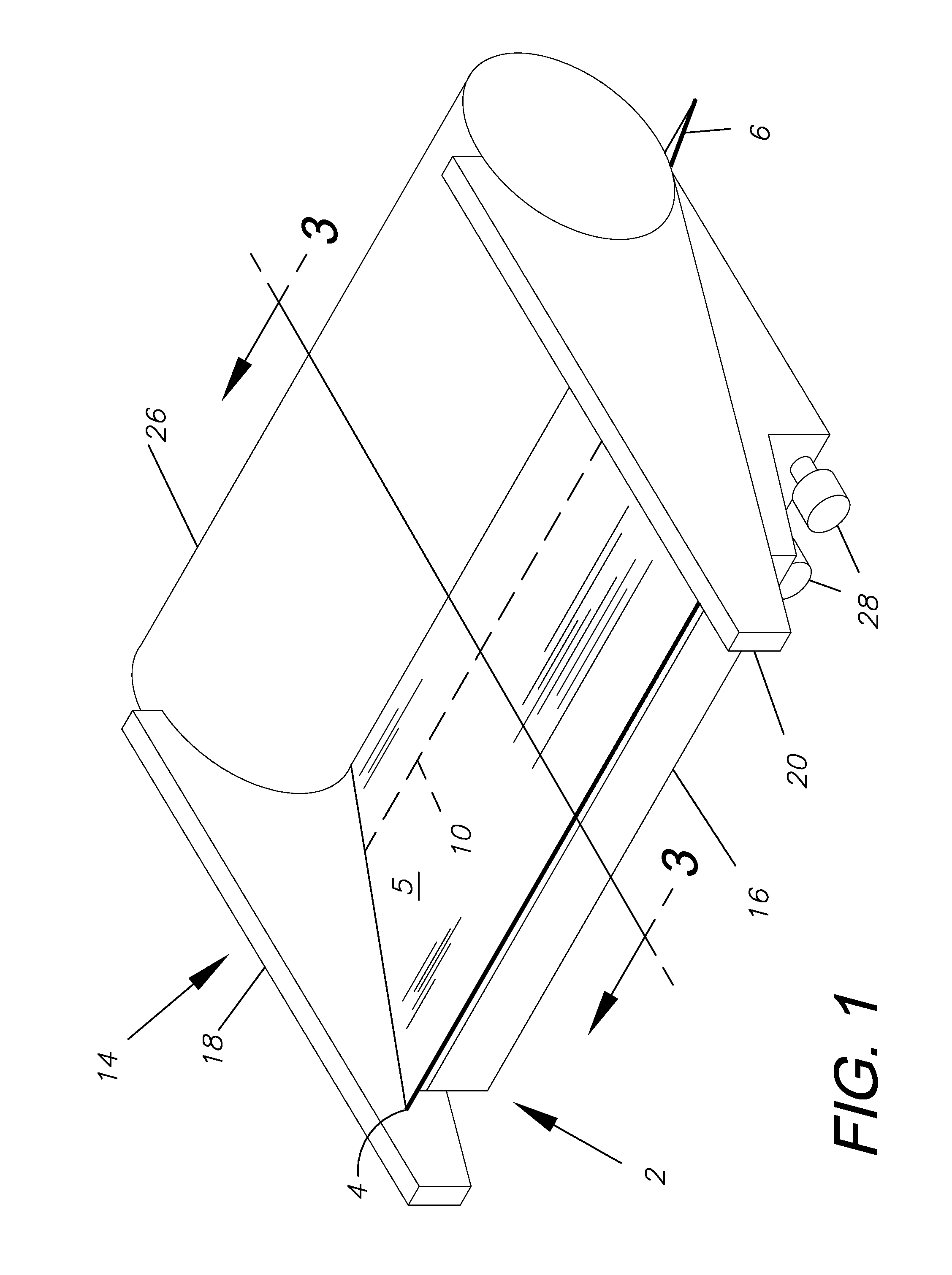
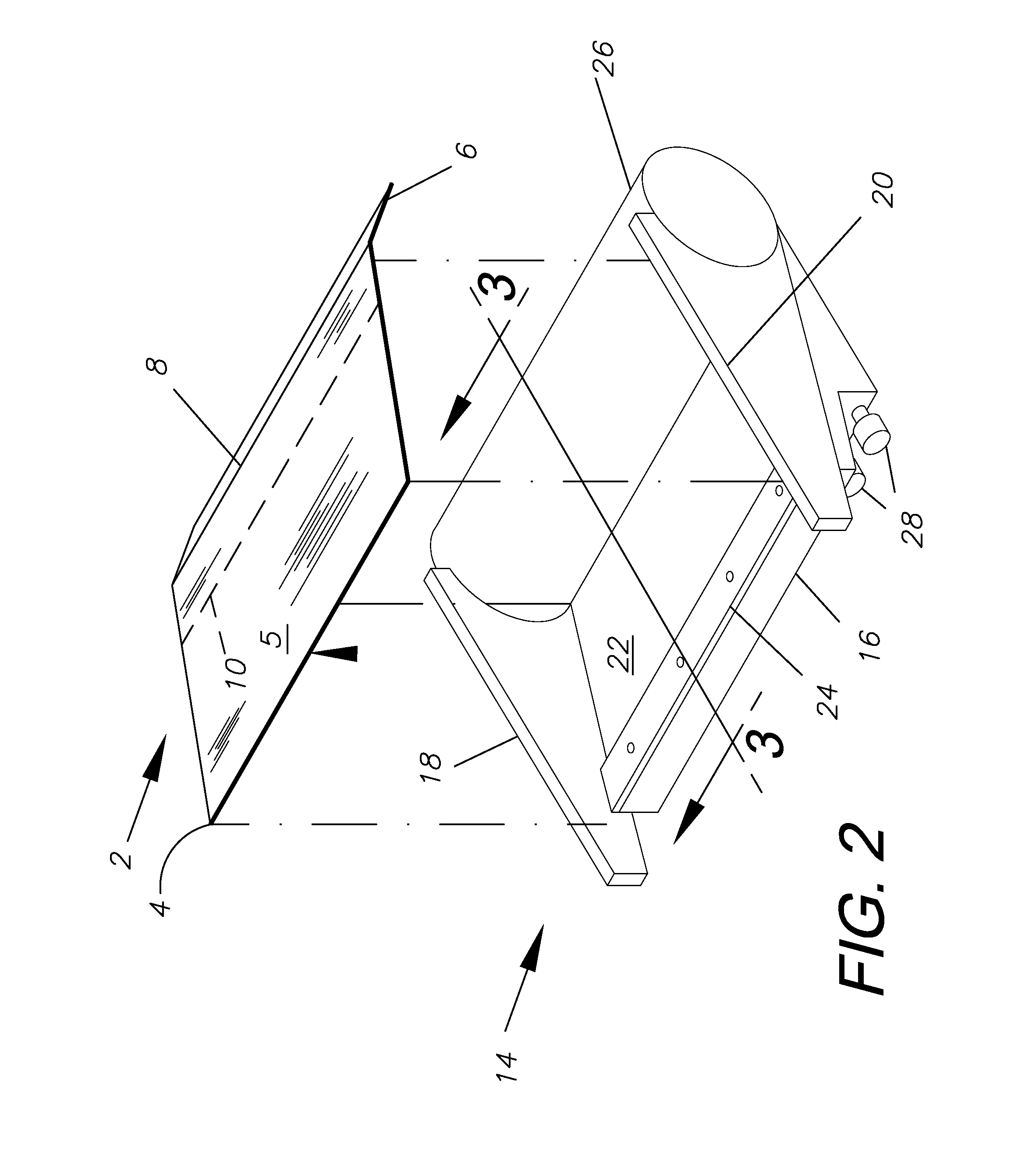
[0024]As shown in FIGS. 1-2, the ink fountain 14 generally comprises a base 16, a left sidewall 18, a right sidewall 20, a blade 22, and a blade retainer 24. The blade retainer 24 keeps the blade 22 in place during use and can be removed for maintenance or replacement of the blade 22. The ink fountain 14 is engaged with an ink roller 26, with the left 18 and right 20 sidewalls of the ink fountain 14 closely adjacent or contacting the ink roller 26.
[0025]FIG. 3 is a sectional view of the present invention and the surrounding environment along section line 3 as shown in FIGS. 1-2. The ink fountain 14 is partly filled with ink 30, which is contained by a top surface 5 of the panel 4 and the ink roller 26.
[0026]FIGS. 4A and 4B are enlarged, sectional views taken generally within Circle 4 in FIG. 3. As shown in FIG. 4A, the front flap 6 acts as a barrier between the blade edge 32 and the ink roller 26. Because the front flap 6 keeps the blade edge 32 and the ink roller 26 from touching, there is no metal-on-metal friction between the blade edge 32 and the ink roller 26, which prevents the ink 30 temperature from increasing and prolongs the life of the blade 22 by preventing irregularities from forming due to contact with the ink roller 26. The blade edge 32 comes in contact with the ink roller 26 when adjustment screws 28 in the base 16 of the ink fountain 14 are tightened to apply pressure at a given point on the blade edge 32. As shown in FIG. 4B, loosening the screws 28 results in a nip 33 between the blade edge 32 and the ink roller 26. The ink roller 26 turns counter-clockwise as viewed from its right side (FIGS. 3, 4A and 4B). Ink on the roller 34 passes through the nip and into the offset press.
[0027]FIG. 5 is an isometric view of the top of the preferred embodiment of the ink fountain liner and the blade guard 2. FIG. 6 is an isometric view of the bottom surface 7 of the ink fountain liner and blade guard 2. The backing strip 12 is peeled away and the adhesive strip 10 is pressed onto the blade 22 to hold the ink fountain liner and blade guard 2 in position on the ink fountain 14.
[0028]FIG. 7 is an isometric view of an alternative embodiment ink fountain liner and blade guard 102 comprising a flat panel 104, a top surface 105, i.e. without a crease, and an adhesive strip 110.
[0029]FIG. 8 is an isometric view of another alternative embodiment ink fountain liner and blade guard 202, a flat panel 204, a top surface 205 with a double-sided adhesive strip 210, and a front flap 206 with a crease 208. A rear flap 236 is connected to the panel 34 at a creased line 238. The rear flap 236 can be used to wipe an ink-handling tool after adding or removing ink 30 from the ink fountain 14.
[0030]FIG. 9 is an isometric view of another alternative embodiment ink fountain liner and blade guard 302. The panel 304 has a top surface 305, a front flap 306, connected at creased line 308, a rear flap 336, connected at creased line 338, a left flap 340, and a right flap 342 connected at creased lines 344, 346. A double-sided adhesive strip 310 is affixed to the outer surface 348 of the side flaps 340, 342 with a backing strip 12 covering the adhesive on the side of the tape not affixed to the outer surface 348. The side flaps 340, 342 keep ink from getting on the left 18 and right 20 sidewalls of the ink fountain 14.
[0031]It will be appreciated that the ink fountain liner and blade guard can be used for various applications not described herein. Moreover, the ink fountain liner and blade guard can be constructed of additional elements or alternative elements to those mentioned herein, while providing similar results.
[0032]It is to be understood that while certain aspects of the disclosed subject matter have been shown and described, the disclosed subject matter is not limited thereto and encompasses various other embodiments and aspects.

PUM

no PUM

Description & Claims & Application Information

We can also present the details of the Description, Claims and Application information to help users get a comprehensive understanding of the technical details of the patent, such as background art, summary of invention, brief description of drawings, description of embodiments, and other original content. On the other hand, users can also determine the specific scope of protection of the technology through the list of claims; as well as understand the changes in the life cycle of the technology with the presentation of the patent timeline. Login to view more.

Similar technology patents

Method for preparing methyl acetate

Owner:YANCHANG ZHONGKE (DALIAN) ENERGY TECH CO LTD

Classification and recommendation of technical efficacy words

  • Prolonged life
  • Prevent from form

Metallic belt and push block used therefor

InactiveUS20070072721A1Ensure strengthProlonged lifeV-beltsGearingSurface frictionOil film
Owner:FUKUJU INDS

Biocompatible Mesh Implant

ActiveUS20130253645A1Increase tolerancePrevent from formMammary implantsBreast implantGeneral surgery
Owner:PFM MEDICAL

Spiral electrodeionization device with uniform operating characteristics

InactiveUS20060163056A1Prevent from formEnhance removalCellsIon-exchange column/bed processesIon exchangeIon
Owner:IONICS INC

Woman's undergarment to remedy chest wrinkles

ActiveUS8047892B1Prevent from formComfortably wearBrassieresWrinkleTorso
Owner:DEMPSEY DARLENE S
Why Eureka
Try Eureka