Optical sensor capable of detecting ir light and visible light simultaneously

a technology of optical sensors and visible light, applied in the field of optical sensors, can solve the problems of reducing product yield, increasing manufacturing costs, and inaccurate results of prior art visible light sensors

Active Publication Date: 2012-09-27
PIXART IMAGING INC
View PDF1 Cites 27 Cited by
  • Summary
  • Abstract
  • Description
  • Claims
  • Application Information

AI Technical Summary

Problems solved by technology

However, the prior art visible light sensor may detect peaks in the non-visible range of the optical spectrum which results in inaccurate results.
For example, when the intensity of ambient light becomes insufficient to human eyes, the prior art visi

Method used


Image

  • Optical sensor capable of detecting ir light and visible light simultaneously
  • Optical sensor capable of detecting ir light and visible light simultaneously
  • Optical sensor capable of detecting ir light and visible light simultaneously

Examples


first embodiment

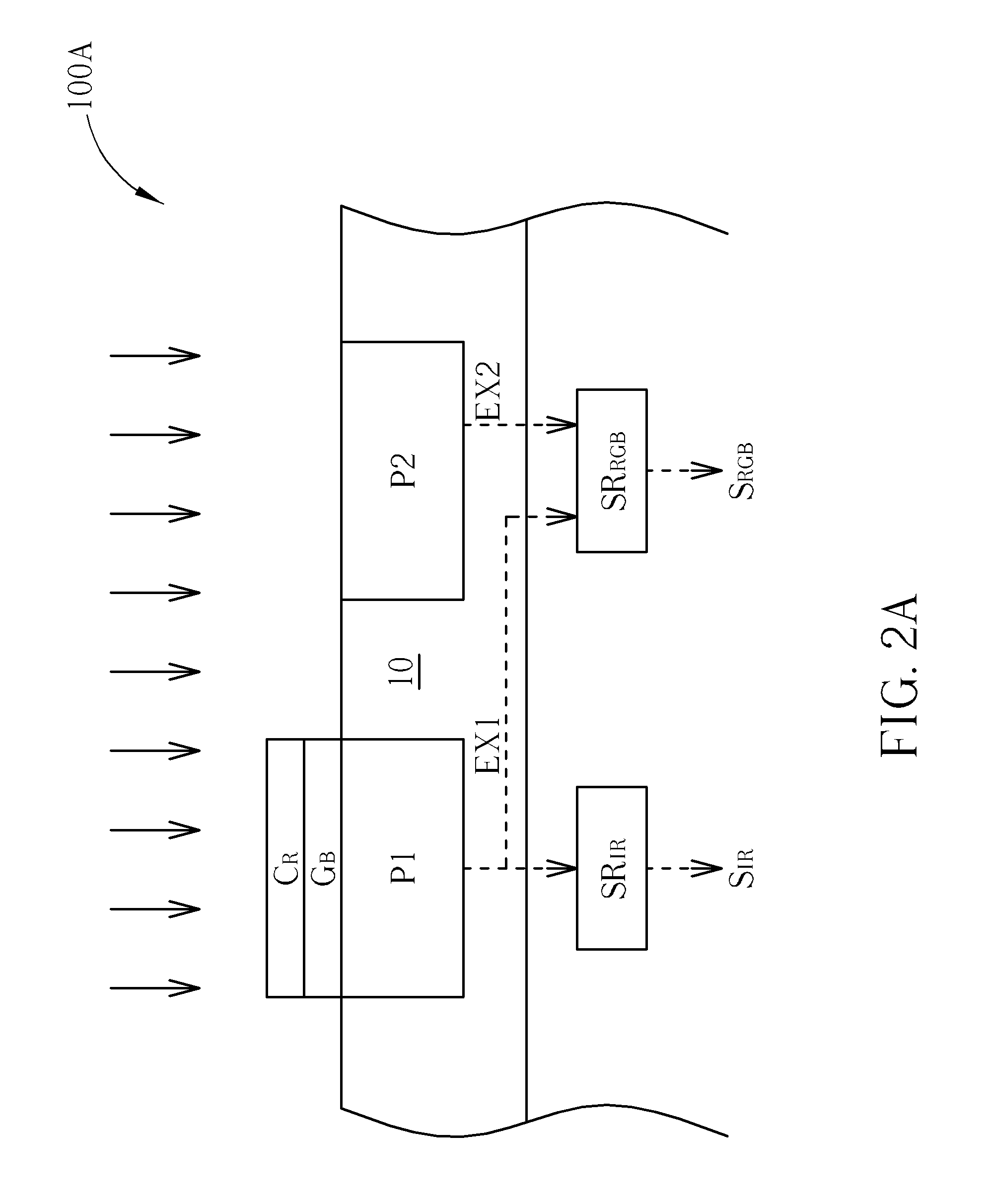
[0020]FIGS. 2A-2C are diagrams illustrating optical sensors 100A-100C according to the present invention. Each of the optical sensors 100A-100C includes an image sensor 10, a proximity sensor SRIR, and a visible light sensor SRRGB. The image sensor 10 includes a pixel P1 coated with two types of optical films and a pixel P2 without any coating. The pixels P1 and P2 of the image sensor 10 may absorb light and generate corresponding electrical signals. The proximity sensor SRIR and the visible light sensor SRRGB are signal processors capable of determining the intensity of visible light or IR light according to the electrical signals received from the pixels P1 and P2.

[0021]In the optical sensor 100A according to the first embodiment of the present invention, the pixel P1 is coated with a red optical film CR and a blue optical film CB, wherein the red optical film CR only transmits the red visible light (i.e. blocking light whose wavelength is not between 600-780 nm) and the blue opti...

second embodiment

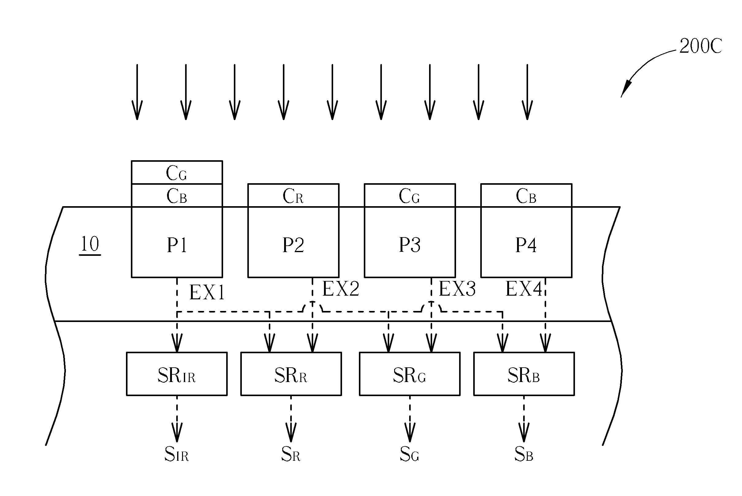
[0026]FIGS. 5A-5C are diagrams illustrating optical sensors 200A-200C according to the present invention. Each of the optical sensors 200A-200C includes an image sensor 10, a proximity sensor SRIR, a red visible light sensor SRR, a green visible light sensor SRG, and a blue visible light sensor SRB. The image sensor 10 includes four pixels P1-P4: the pixel P1 is coated with two types of optical films, while each of the pixels P2-P4 is coated a specific type of optical film. The pixels P1-P4 of the image sensor 10 may absorb light and generate corresponding electrical signals. The proximity sensor SRIR, the red visible light sensor SRR, the green visible light sensor SRG, and the blue visible light sensor SRB are signal processors capable of determining the intensity of each visible light or IR light according to the electrical signals received from the pixels P1-P4.

[0027]In the optical sensor 200A according to the second embodiment of the present invention, the pixel P1 is coated wi...


PUM


Abstract

An optical sensor includes an image sensor, a proximity sensor and a visible light sensor. The image sensor includes a first pixel and a second pixel. The first pixel is coated with a first optical film for blocking light whose wavelength is outside a first predetermined range and a second optical film for blocking light whose wavelength is outside a second predetermined range. The proximity sensor generates an IR signal according to a first exposure value. The visible light sensing unit generates a visible light signal according to the difference between the first exposure and a second exposure value or according to a ratio of the first exposure value to the second exposure value. The first exposure value represents an incident light quantity which is absorbed by the first pixel. The second exposure value represents an incident light quantity which is absorbed by the second pixel.

Description

BACKGROUND OF THE INVENTION[0001]1. Field of the Invention[0002]The present invention is related to an optical sensor, and more particularly, to an optical sensor capable of detecting IR light and visible light simultaneously.[0003]2. Description of the Prior Art[0004]Light is the portion of electromagnetic radiation whose wavelength is between 300 nm (ultraviolet) to 14,000 nm (far infrared). The wavelength of visible light lies in a range from about 380 to about 780 nm. Infrared radiation (IR) is the portion of electromagnetic radiation whose wavelength is between 780 nm to 1400 nm. With high thermal efficiency, strong penetration and easy absorption, IR imaging is used extensively for communication, probing, medical and military purposes.[0005]An optical sensor is used for converting optical signals into electrical signals using an image sensor capable of detecting light in a wavelength range of 400-1000 nm. Visible light sensors are commonly used for controlling environmental br...

Claims


Application Information

Patent Timeline
IPC IPC(8): H01L27/146
CPCH01L27/1462H01L27/14647H01L27/14621H01L27/14625H01L27/14645H01L27/14649
Inventor HSU, EN-FENGLIAO, CHI-CHIEH
Owner PIXART IMAGING INC
Why Eureka
Try Eureka