System, method, and filter for target tracking in cartesian space

a cartesian space and target tracking technology, applied in the field of angleonly tracking filters, can solve the problems of poor estimation performance of conventional msc filters, and achieve the effect of accurately determining the position, velocity and acceleration of targets

Active Publication Date: 2012-09-27
RAYTHEON CO
View PDF2 Cites 7 Cited by
  • Summary
  • Abstract
  • Description
  • Claims
  • Application Information

AI Technical Summary

Benefits of technology

[0005]Aspects according to embodiments of the present invention use sample angle measurements of a moving target and ownship kinematics to accurately determine the target's position, velocity, and acceleration.

Problems solved by technology

However, conventional MSC filters perform poorly when estimating a rapidly accelerating target's position, velocity, and acceleration.

Method used


Image

  • System, method, and filter for target tracking in cartesian space
  • System, method, and filter for target tracking in cartesian space
  • System, method, and filter for target tracking in cartesian space

Examples


Embodiment Construction

.”

BRIEF DESCRIPTION OF THE DRAWINGS

[0021]Features, aspects, and embodiments are described in conjunction with the attached drawings, in which:

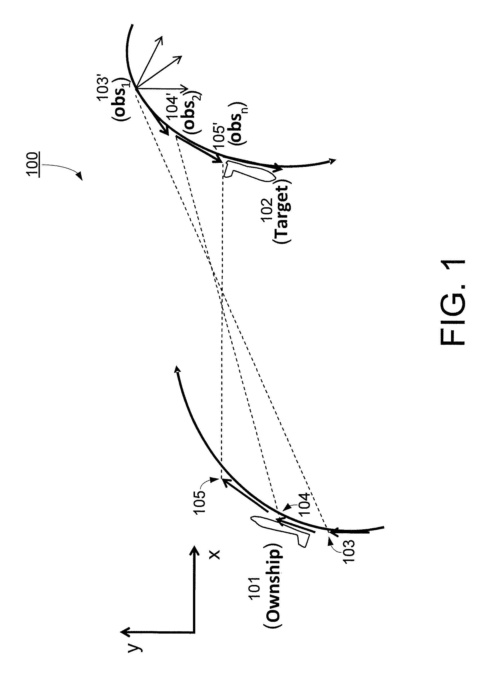
[0022]FIG. 1 is an illustration of target-to-ownship observations according to an embodiment of the present invention.

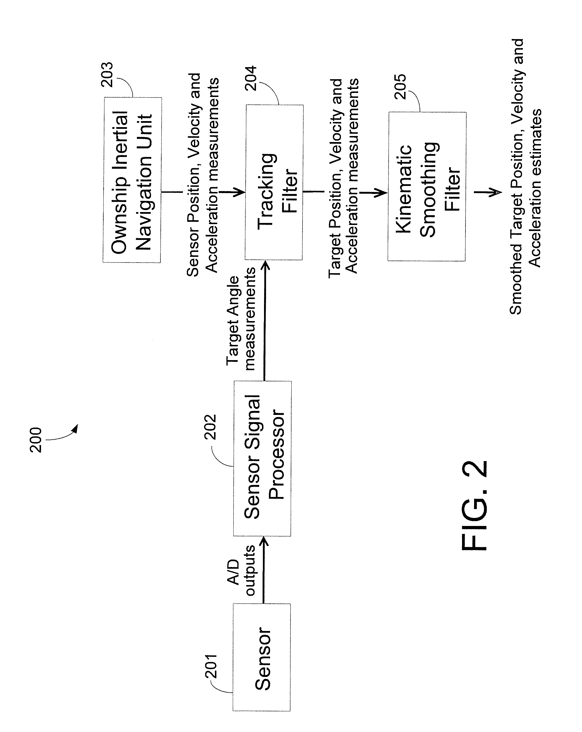
[0023]FIG. 2 is a system-level block diagram of an angle-only tracking system according to an embodiment of the present invention.

[0024]FIG. 3. is a block diagram of an angle-only tracking filter, which can be included in FIG. 2, according to an embodiment of the present invention.

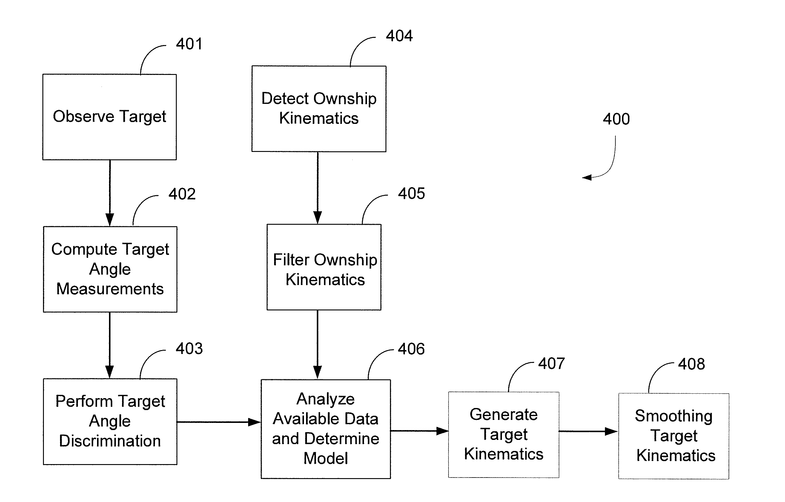
[0025]FIG. 4 is a flow chart of a method of angle-only tracking according to an embodiment of the present invention.

DETAILED DESCRIPTION

[0026]A particle's motion in the absence of external and / or internal forces is typically described by the defining relation:

r→t=v→(Eq.1)

[0027]Where {right arrow over (r)} and {right arrow over (v)} correspond to the particle's three dimensional position and velocity respectively. The typical treatment of this system i...


PUM


Abstract

An angle-only tracking filter includes: a target angle discriminant unit configured to receive sensor signal outputs and form angle only observations of a target relative to an ownship; an ownship navigation filter configured to receive and filter ownship inertial navigation measurements; a model analyzer configured to receive and analyze the ownship inertial navigation measurements and select the order of target kinematics to be determined; and a target kinematics generator coupled to the angle discriminant unit, the navigation filter unit, and the model analyzation unit, including: a first-order filter unit configured to generate a target position from the target angle measurements and the ownship inertial navigation information; a second-order filter unit configured to generate a target velocity from the target angle measurements and the ownship inertial navigation information; and a third-order filter unit configured to generate a target acceleration from the target angle measurements and the ownship inertial navigation information.

Description

BACKGROUND[0001]1. Field[0002]Embodiments described herein relate in general to angle-only tracking filters.[0003]2. Description of Related Art[0004]When a rapidly moving target is being tracked it is advantageous to precisely determine the position, velocity, and acceleration of the target. Based on relative (ownship-to-target) angle observations, angle-only filters such as a conventional Modified Spherical Coordinate (MSC) filters have success in estimating the range of the target. However, conventional MSC filters perform poorly when estimating a rapidly accelerating target's position, velocity, and acceleration.SUMMARY[0005]Aspects according to embodiments of the present invention use sample angle measurements of a moving target and ownship kinematics to accurately determine the target's position, velocity, and acceleration.[0006]Additionally, aspects according to embodiments of the present invention also incorporate nth order kinematics equations to improve the prediction accur...

Claims


Application Information

Patent Timeline
Patent Type & Authority Applications(United States)
IPC IPC(8): G01S13/44
CPCG01S13/68G01S13/44
Inventor ROJAS, RANDALL R.HIROSHIGE, JAMES J.
Owner RAYTHEON CO
Why Eureka
Try Eureka