
Cover, electronic device rack, and air conditioning system

a technology for electronic devices and air conditioning systems, applied in electrical appliances, lighting and heating equipment, cooling/ventilation/heating modifications, etc., can solve the problems of increasing the heat generated by electronic devices, reducing and generating a great amount of heat, so as to achieve the effect of improving the air conditioning efficiency of computer rooms

Inactive Publication Date: 2012-09-27
NEC CORP
View PDF12 Cites 11 Cited by
  • Summary
  • Abstract
  • Description
  • Claims
  • Application Information

AI Technical Summary

Benefits of technology

[0008]An exemplary object of the invention is to easily improve the air conditioning efficiency of a computer room.

Problems solved by technology

These electronic devices generate a great amount of heat.
However, as the servers and the like have grown more powerful, the amount of heat generated by them has increased.
In the above-described arrangement, the air conditioning efficiency consequently lowers because the cold air from under the floor mixes with the warm air exhausted from the electronic devices.
This may lead to formation of points where the heat partially concentrates (to be referred to as “hot spots” hereinafter), resulting in failures in the electronic devices.
However, to apply the arrangement of literature 1 to a computer room, it is necessary to rearrange the racks and stop the servers for this rearrangement, requiring much labor and high cost.
This makes the number of rack lines that can be arranged in the computer room smaller than usual and thus leads to a decrease in the number of electronic devices that can be installed in the computer room.
In addition, installing the ceiling air ducts is also required.

Method used


Image

  • Cover, electronic device rack, and air conditioning system
  • Cover, electronic device rack, and air conditioning system
  • Cover, electronic device rack, and air conditioning system

Examples


first exemplary embodiment

[0018]The first exemplary embodiment of the present invention will be described first.

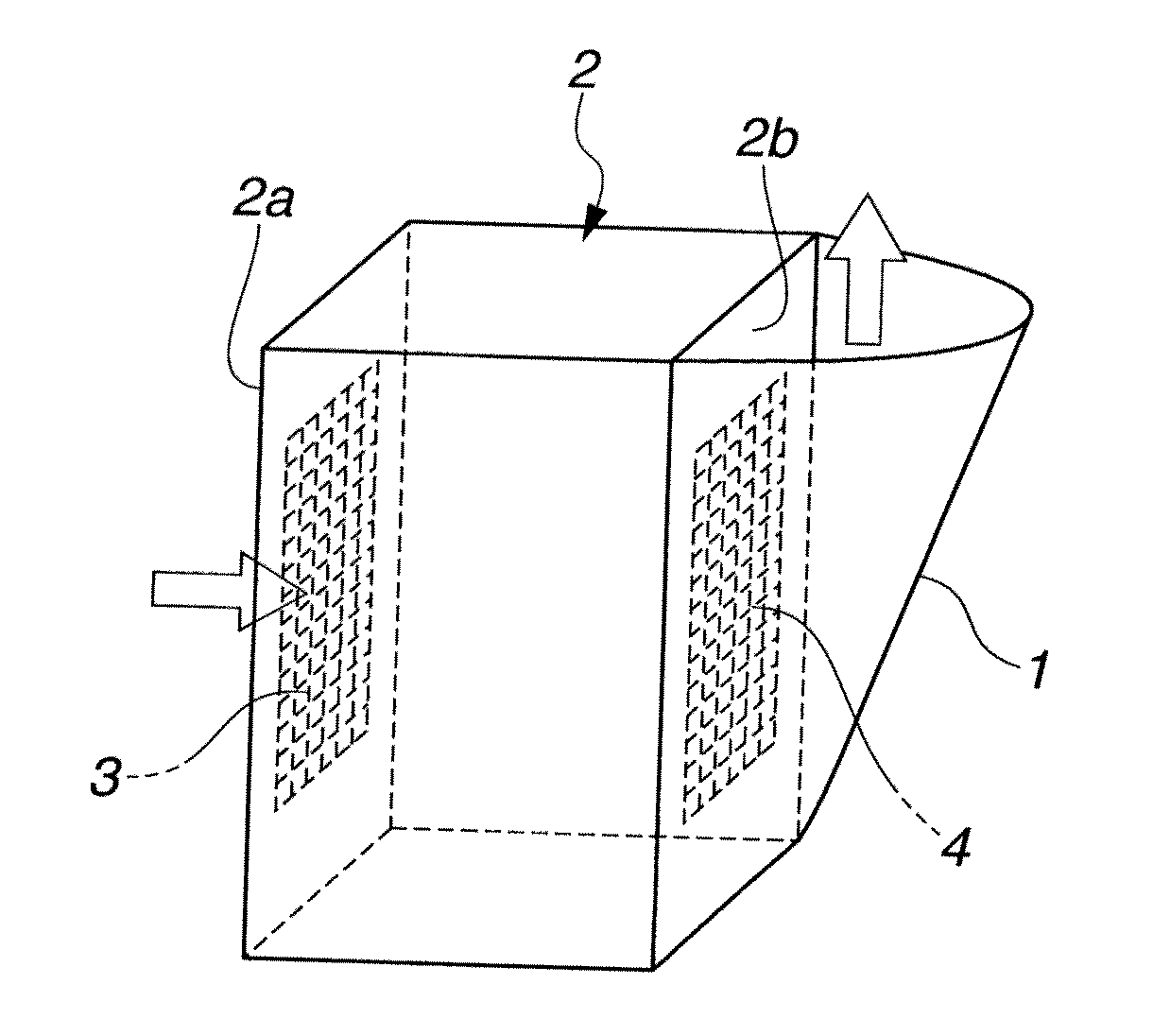
[0019]As shown in FIG. 1, a cover according to the first exemplary embodiment is formed from a sheet-shaped member (sheet). The cover 1 is attached to a rear surface (one surface) 2b of a rack 2 that accommodates electronic devices. The rear surface 2b of the rack 2 is provided with an outlet 4. The cover 1 guides exhaust air from the outlet 4 upward (in one direction along the rear surface of the rack).

[0020]Providing the cover 1 makes it possible to separate supplied cold air and warm air exhausted from the electronic devices from each other even in a computer room where a front surface 2a of one rack 2 provided with an inlet 3 is arranged so as to face the rear surface 2b of the other rack 2 provided with the outlet 4. For this reason, hot spot formation can be prevented without rearranging the racks 2 that accommodate the electronic devices or stopping the servers for the rearrangement. This al...

second exemplary embodiment

[0022]The second exemplary embodiment of the present invention will be described next.

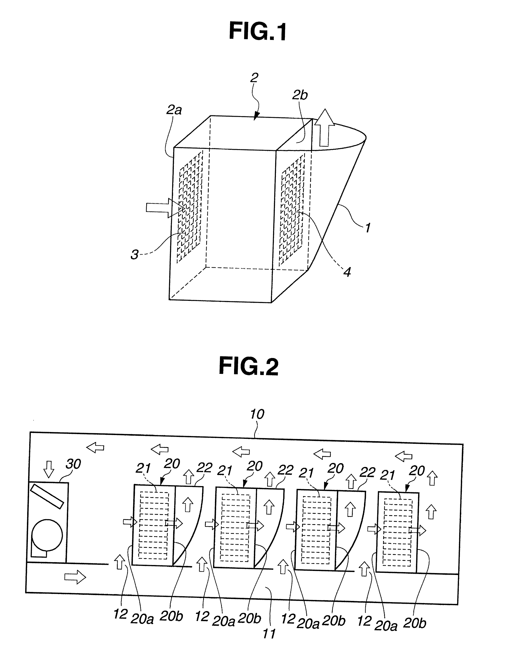
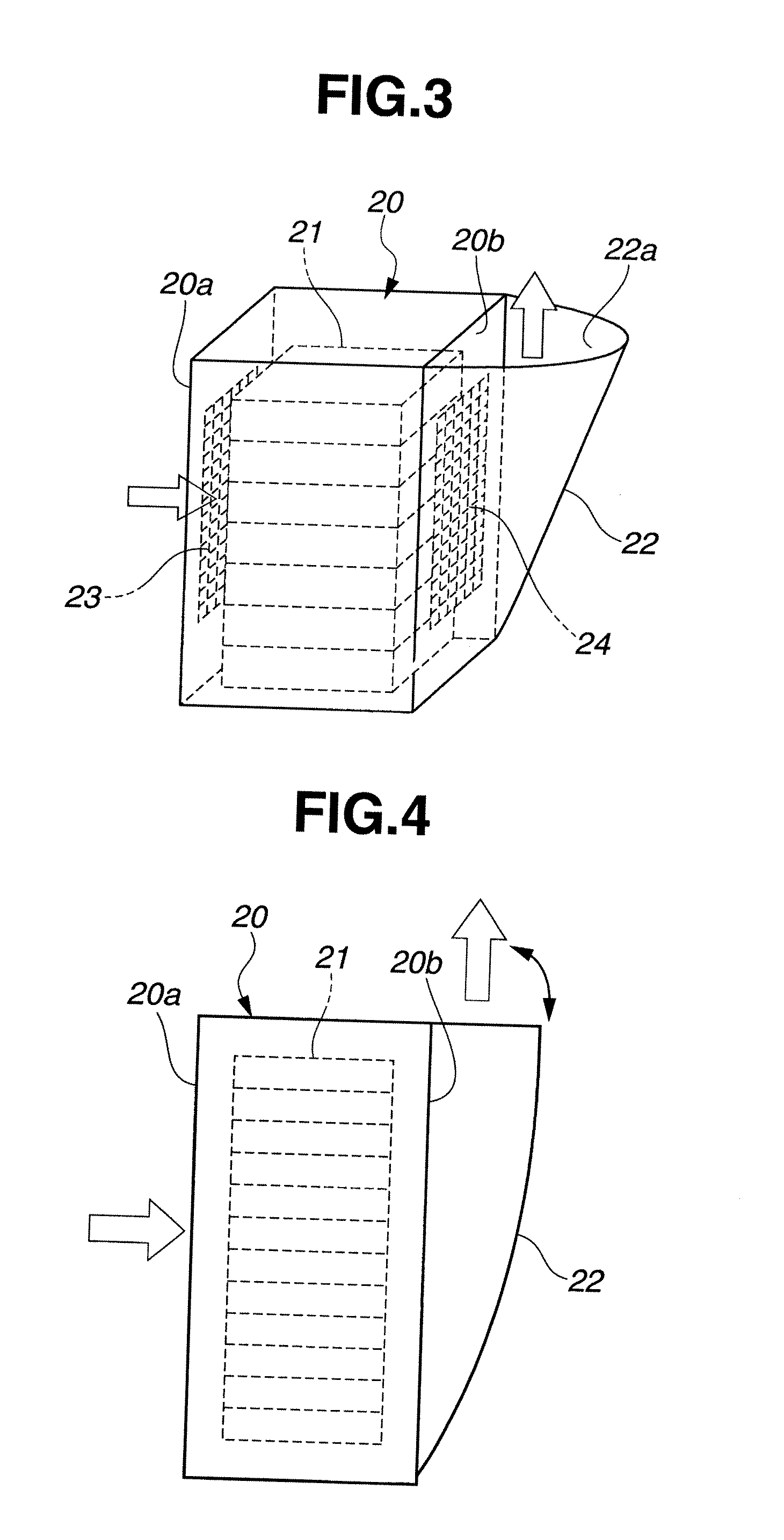
[0023]As shown in FIG. 2, an air conditioning system according to the second exemplary embodiment is applied to a computer room 10 where a number of racks 20 are installed. The racks 20 are arrayed in a plurality of lines. The racks 20 facing each other in lines adjacent to each other are arranged such that an air-sucking front surface 20a of one rack 20 faces an air-exhausting rear surface 20b of the other rack 20.

[0024]The computer room 10 has a double floor structure. An underfloor air-conditioning space 11 is provided between the upper floor surface and the lower floor surface. An outlet of an air conditioner (air conditioning apparatus) 30 is connected to the underfloor air-conditioning space 11. The upper floor surface is provided with a plurality of underfloor air outlets 12. The positions of the underfloor air outlets 12 correspond to the positions of the racks 20. The underfloor air outlet...


PUM


Abstract

A cover is provided on one surface of a rack of an electronic device provided with an outlet, and includes a sheet that guides exhaust air exhausted from the outlet in one direction along the one surface. An electronic device rack and an air conditioning system are also disclosed.

Description

[0001]This application is based upon and claims the benefit of priority from Japanese patent application No. 2011-067424, filed on Mar. 25, 2011, the disclosure of which is incorporated herein in its entirety by reference.BACKGROUND OF THE INVENTION[0002]The present invention relates to a cover, an electronic device rack, and an air conditioning system provided in a computer room where a plurality of racks are installed.[0003]In a computer room, a number of electronic devices such as a server and a router are installed in the same space. These electronic devices generate a great amount of heat. To prevent the heat from causing failures in the electronic devices, an air conditioner is provided in the computer room. A general air conditioner supplies cold air from under the floor of the computer room and exhausts warm air from the ceiling portion of the computer room. Many electronic devices are mounted in 19-inch standard racks. In this case, the cooling air is supplied from the fron...

Claims


Application Information

Patent Timeline
IPC IPC(8): H05K7/20F28F13/06
CPCH05K7/20745H05K7/20736
Inventor OKADA, KEIICHI
Owner NEC CORP
Learn More