
Control apparatus and control method for electrically driven vehicle

a technology of electrical drive and control apparatus, which is applied in the direction of electric devices, process and machine control, instruments, etc., can solve the problems of insufficient improvement of vehicle traveling stability, and achieve the effect of reducing the effective radius and reducing the torqu

Active Publication Date: 2012-09-27
NTN CORP
View PDF4 Cites 14 Cited by
  • Summary
  • Abstract
  • Description
  • Claims
  • Application Information

AI Technical Summary

Benefits of technology

[0008]In view of the foregoing, an object of the present invention is to provide a control device for an electrically powered vehicle of a type, in which even when the effective radii differ between left and right vehicle wheels because of a change in, for example, a tire pneumatic pressure in one or both of the vehicle wheels, the difference in driving forces between the left and right vehicle drive wheels can be zeroed to suppress generation of the turning force to thereby improve the vehicle traveling stability, and, also, to provide a method of so controlling in the electrically powered vehicle.
[0030]In such case, in a manner similar to that described in connection with the first mentioned aspect of the present invention that provides the control device of the type, in which the torque control is performed, one of the drive wheels, whose rotation ratio between the detected numbers of revolutions of the drive wheel and the theoretical number of revolutions is greater than that of the other drive wheel is regarded as having a reduction in effective radius and correction is therefore made to reduce the torque and, accordingly, the neutral steer condition can be maintained and the generation of the turning force resulting from the presence of the difference in effective radius between the left and right drive wheels can be suppressed.

Problems solved by technology

For this reason, an improvement in vehicle traveling stability is insufficient.

Method used


Image

  • Control apparatus and control method for electrically driven vehicle
  • Control apparatus and control method for electrically driven vehicle
  • Control apparatus and control method for electrically driven vehicle

Examples


Embodiment Construction

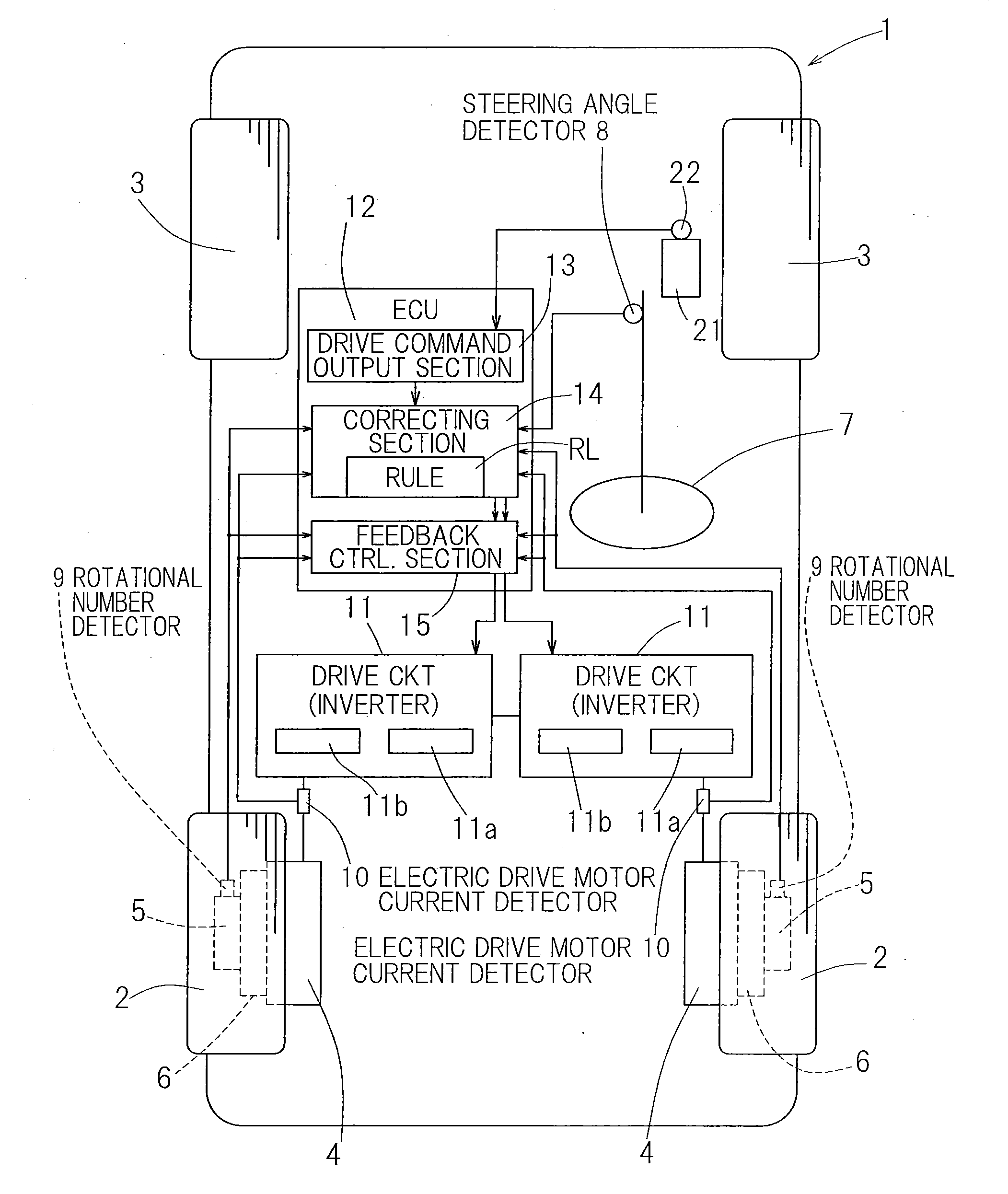
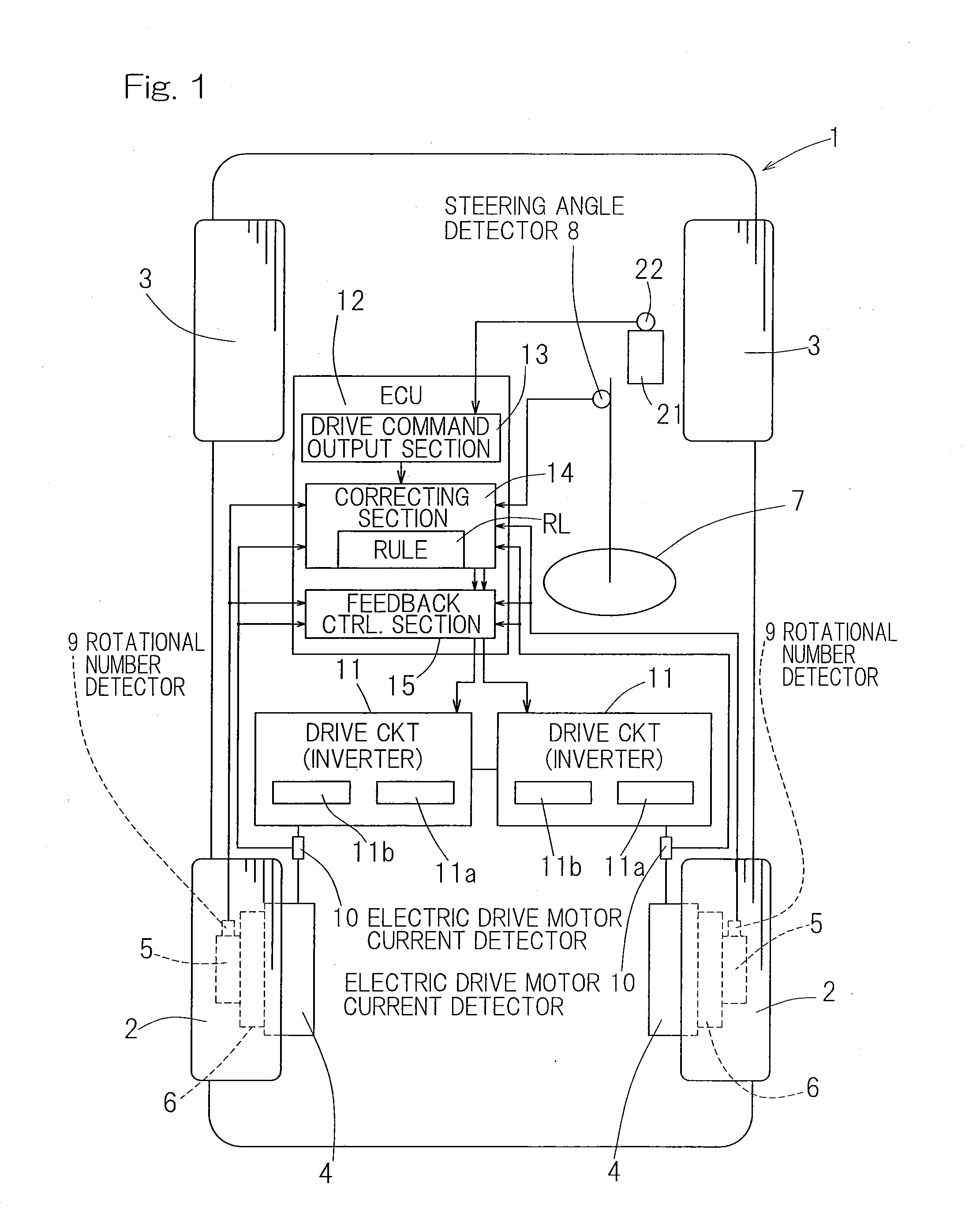
[0034]A preferred embodiment of the present invention will now be described in detail with reference to the accompanying drawings. FIG. 1 illustrates a conceptual construction of an electrically powered vehicle equipped with a control device for the electrically powered vehicle designed in accordance with the preferred embodiment of the present invention. The electrically powered vehicle, hereinafter referred to as a vehicle 1, is a four wheeled automotive vehicle including left and right rear wheels, which are rendered to be vehicle drive wheels 2, and left and right front wheels, which are rendered to be vehicle driven and steering wheels 3. Each of those drive and driven wheels 2, 3 is a wheel having a corresponding tire (not shown). The left and right drive wheels 2 and 2 are driven by respective electric drive motors 4 and 4 that are separate and independent from each other. Each of those drive wheels 2 is supported by a vehicle body structure of the vehicle 1 through respectiv...


PUM


Abstract

Even when the effective radii of wheels differ from each other because of a change in tire pneumatic pressure, the difference in driving force between left and right drive wheels are substantially zeroed to suppress a turning force to thereby increase the traveling stability. The use is made of a corrector for correcting a command value to be outputted to a drive circuit for an electric drive motor for each of the drive wheels. This corrector receives the steering angle, the respective numbers of revolutions of the drive wheels and an electric drive motor current and corrects with the use of the steering angle as measured with respect to a traveling direction so that command values relative to the drive wheels may have such a relation that the turning force induced in a vehicle as a result of the difference in effective radius between the drive wheels can be suppressed.

Description

CROSS REFERENCE TO THE RELATED APPLICATION[0001]This application is a continuation application, under 35 U.S.C. §111(a), of international application No. PCT / JP2010 / 071822, filed Dec. 6, 2010, which claims priority to Japanese patent application No. 2009-281210, filed Dec. 11, 2009, the entire disclosure of which is herein incorporated by reference as a part of this application.BACKGROUND OF THE INVENTION[0002]1. Field of the Invention[0003]The present invention relates to the control of an electrically driven vehicle such as, for example, an automotive vehicle of a kind having left and right, independent drive motors.[0004]2. Description of Related Art[0005]The electric motorcar now attracting public attentions is considered a high performance vehicle as it makes use of left and right electric motors such as, for example, in-wheel motors that can be controlled independently from each other. In most of the electric motorcars currently available in the market, the electric motors emp...

Claims


Application Information

Patent Timeline
IPC IPC(8): B60L15/20
CPCB60K1/02Y02T10/7275B60K7/0007B60K2007/0038B60L15/20B60L2220/44B60L2240/24B60L2240/423B60T2240/07B60W10/08B60W30/18145B60W2510/083Y02T10/646Y02T10/648B60K7/00Y02T10/72B60L15/2036Y02T10/64B60W2540/18
Inventor OKADA, KOICHIMAKINO, YUSUKE
Owner NTN CORP
Learn More