Orbital surface cleaning apparatus

a surface cleaning and orbital technology, applied in the direction of carpet cleaners, instruments, photosensitive materials, etc., can solve the problems of difficult use of the device, heavy weight, and bulky operation of the conventional orbital surface cleaning device and the rotational surface cleaning device, so as to increase the user's ability to steer the device in use, the effect of reducing the transmission of vibration

Active Publication Date: 2012-10-04
HRUBY JEFFREY T
View PDF14 Cites 17 Cited by
  • Summary
  • Abstract
  • Description
  • Claims
  • Application Information

AI Technical Summary

Benefits of technology

[0019]The device herein disclosed and described provides a solution to the shortcomings in prior art and achieves the above noted goals through the provision of an orbital floor cleaning device and system allowing an improved method for employment with multiple types of floor surfaces. The device employs a folding handle assembly having handle grips which in operative positioning are traverse to the direction of the assembly formed by members communicating with a frame rotationally engaged to the orbital cleaning head assembly. The traverse positioning minimize the transmitted vibration from the head assembly and increase the user's ability to steer the device in use, and provide a means for ergonomic positioning of the user's hands during use.

Problems solved by technology

Such conventional orbital as well as rotational surface cleaning devices, tend to be heavy, bulky, and cumbersome to operate, even with exceptional knowledge of the device.
It is widely known that orbital floor cleaning devices in particular tend to exacerbate the negative aspects commonly associated with floor cleaning devices due to the need to balance the oscillation and rotation of the drive plate.
Unfortunately, manufacturers continue to produce such devices which must be formed in a manner to be heavy in order to counterbalance vibrational and rotational motions of the weights which must be employed to counter balance the weight of the polishing and cleaning component.
The result is a difficult-to-use device that provides an uncomfortable experience for the user.
For example, U.S. Pat. No. 5,355,542 to Oreck et al. titled “Orbiter Floor Apparatus”, granted Oct. 18, 1994, describes a floor cleaning device that is bulky, difficult to use, and is prone inherently to vibrate excessively, and lacks sufficient performance (insufficient dirt extraction, cleaning).
One issue with the device to Oreck is that the configuration of the various components and weights on one side surface of a flywheel are required to achieve the desired orbital motion.
The result is therefor a device which is difficult to handle, prone to damaging the surface being cleaned if not turned by an experienced user, and lacking in user comfort.
Such approaches are considered disadvantageous because the parts employed to create the orbital motion also create numerous stresses and vibrations during use in the planes both normal to and parallel to the flywheel and drive plate.
Over extended period of use, the flywheel and other components can potentially break apart due to such stresses.
Another issue with the device of Oreck and similar devices is that they fail to meet the industry standards as a deep cleaner for carpets and rugs (see the Carpet and Rug Institute Seal of Approval Program at www.carpet-rug.org) This limits the desirability of such a device in many industries including hotels, motels, theme parks, and other locations where meeting industry standards are desired.
This positioning limits the user ability to maneuver the device around obstacles while changing directions, performing maintenance, and overall comfort during use.
Such a configuration, providing an inline communication with the operative head, will also transmit vibrations from the cleaning head to the handles more easily, and is further undesirable in that manner.
Still further, the device to Oreck and others do not provide an device that may partially rest on wheels during operation of the machine, due to the nature of their operation and turning, making it difficult to guide and maneuver prior art polishers during operation.
In addition, many devices employ liquid dispensers which rely on a gravity-fed cleaning solution dispenser, which can lead to over wetting and lack of moisture control on the work surface.
In addition, it has yet to be appreciated that an orbital floor cleaning device can meet industry standards and requirements for all work surface types (e.g., carpets, rugs, hard floors, concrete, wood, stone, tile, grout, brick, vinyl / fcv / linoleum, etc).
Various limitations of the related art will become apparent to those skilled in the art upon a reading and understanding of the specification below and the accompanying drawings.

Method used


Image

  • Orbital surface cleaning apparatus
  • Orbital surface cleaning apparatus
  • Orbital surface cleaning apparatus

Examples


Embodiment Construction

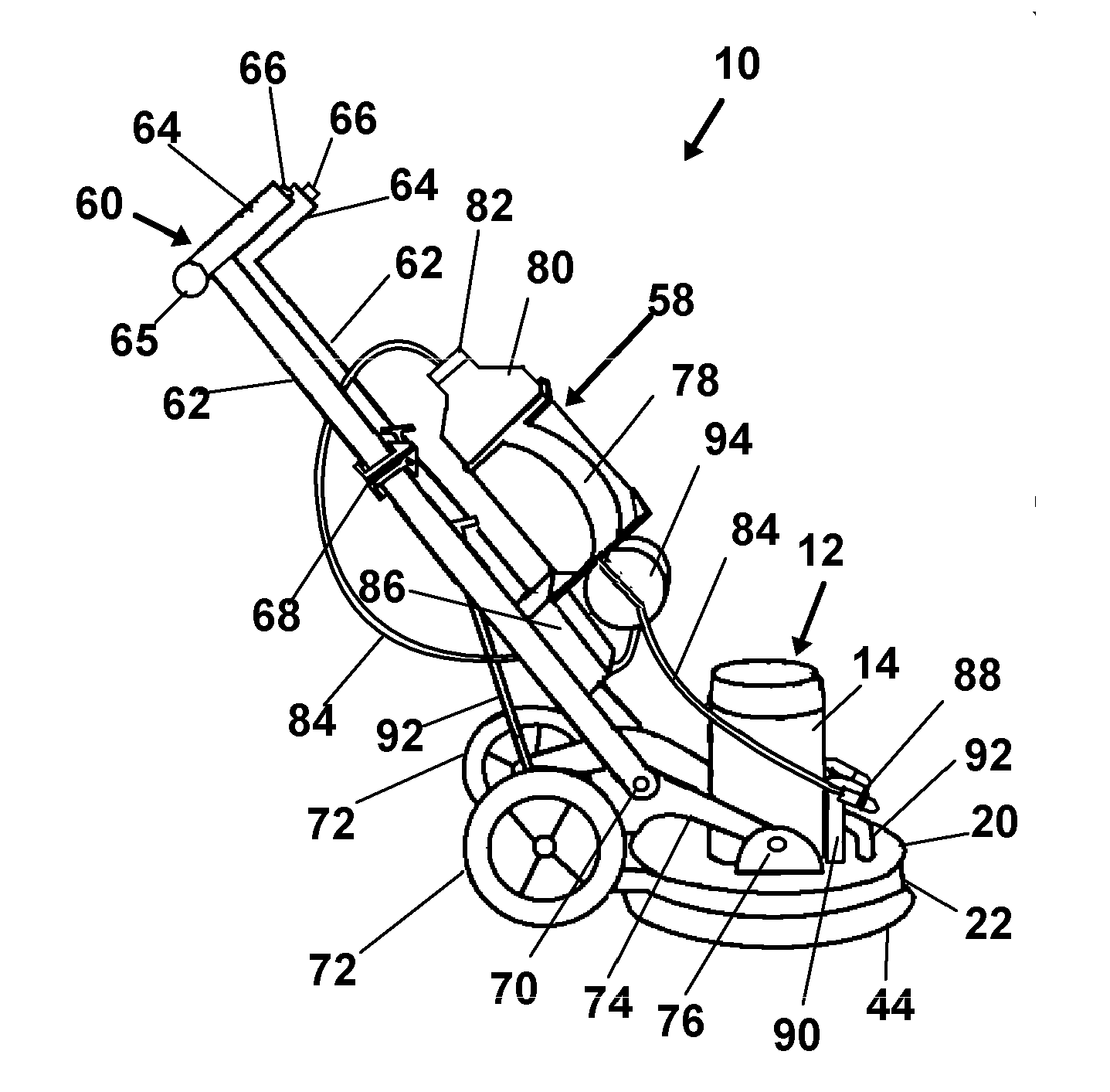
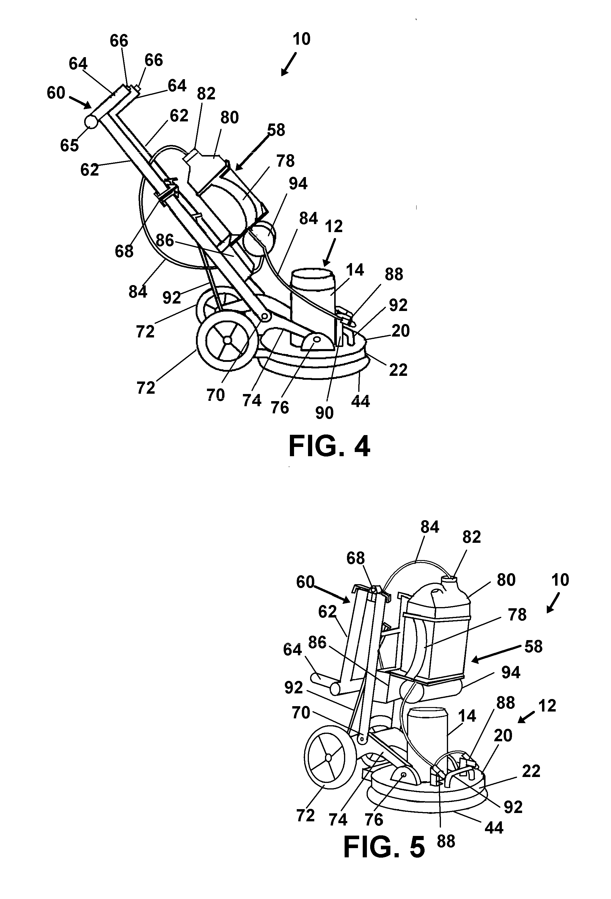
[0051]In this description, the directional prepositions of up, upwardly, down, downwardly, front, back, top, upper, bottom, lower, left, right and other such terms refer to the device as it is oriented and appears in the drawings and are used for convenience only; they are not intended to be limiting or to imply that the device has to be used or positioned in any particular orientation.

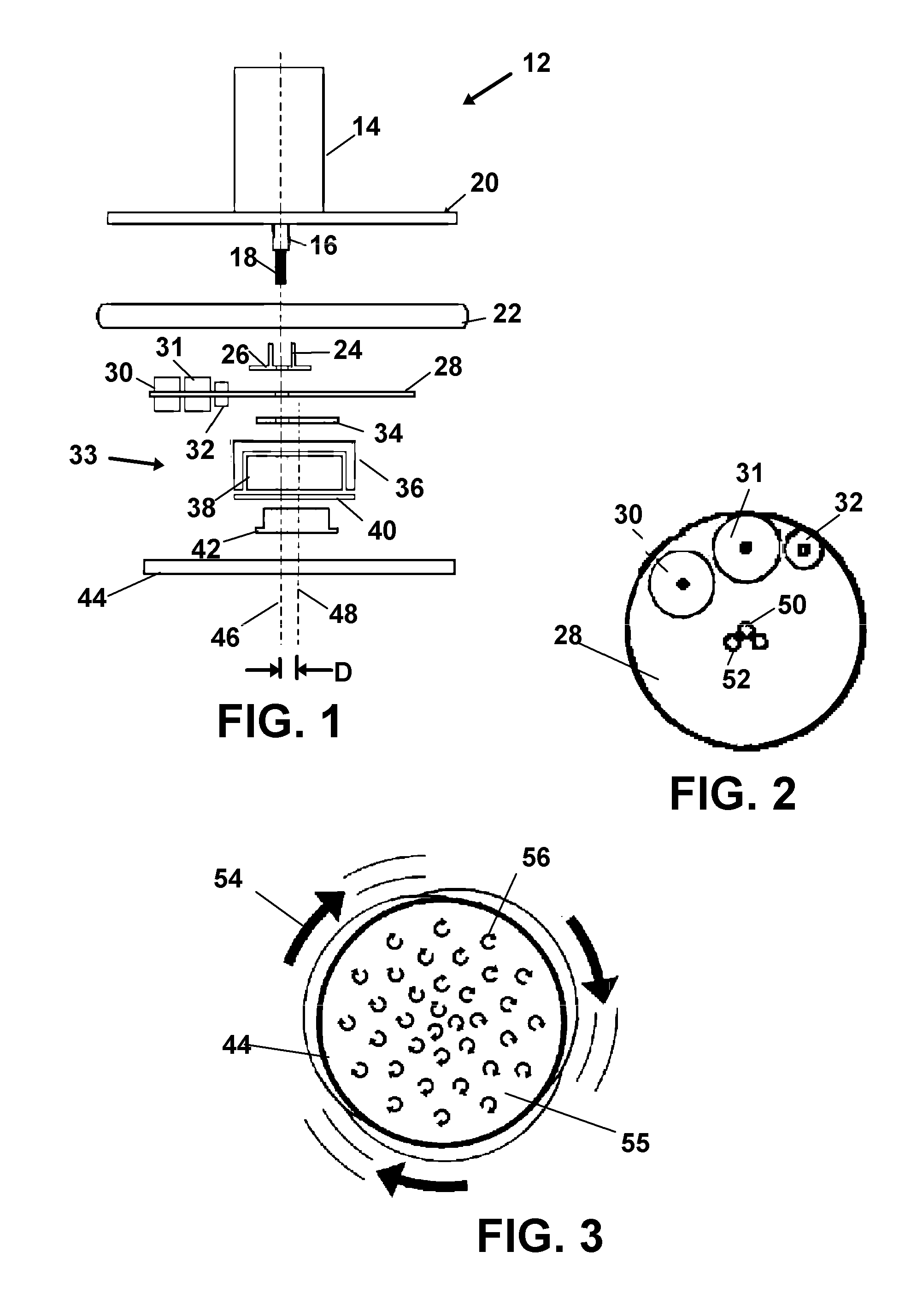
[0052]Various elements or parts of the disclosed device can be configured to be easily replaceable with like-configured parts in situ, thus allowing for modification of the device by an unskilled user. Parts of the system can be easily removed through one or more mechanical connectors, possibly comprising wing nuts, hook-and-loop fasteners (e.g., Velcro™), or other mechanical connectors as would occur to those in the art such as any of those in the 2009 GRANGER fastener catalog M-Q504-07E 8SP2803 which in made part hereof. Any fastener herein can be considered substitutable by the appropriate fastener...


PUM


Abstract

A floor treatment device having a handle assembly having a pair of handles at one end and a rotational engagement to a frame at the other. A head assembly, having a motor and flywheel and offset drive for a pad, is rotationally engaged to the frame to allow all the components to tilt over uneven surfaces. The handles are positioned vertically to provide an ergonomic grip for users. Enhanced orbital operation of the cleaning or other pad is yielded by system of paired weights on the flywheel. A spray system is also engageable to the device.

Description

BACKGROUND OF THE INVENTION[0001]1. Field of the Invention[0002]This application is a continuation in part application of U.S. application Ser. No. 13 / 515,176 filed on Jun. 11, 2012 which claims priority to International Application PCT / US09 / 68467 filed on Dec. 11, 2009, which claims priority to U.S. provisional application Ser. No. 61 / 472271 filed on Apr. 6, 2009 all of which are respectively incorporated herein in their entirety by this reference thereto.[0003]These and all other extrinsic materials discussed herein are incorporated by reference in their entirety. Where a definition or use of a term in an incorporated reference is inconsistent or contrary to the definition of that term provided herein, the definition of that term provided herein applies and the definition of that term in the reference does not apply.[0004]The present invention relates to surface cleaning device. More particularly the invention relates to orbital surface cleaning devices.[0005]2. Prior Art[0006]Con...

Claims


Application Information

Patent Timeline
Patent Type & Authority Applications(United States)
IPC IPC(8): A47L11/02
CPCA47L11/1625A47L11/164A47L11/32A47L11/4083A47L11/4069A47L11/4075A47L11/4061A47L11/4038A47L11/4055A47L11/12A47L11/14A47L11/162
Inventor HRUBY, JEFFREY T.
Owner HRUBY JEFFREY T
Why Eureka
Try Eureka