
Recoil, sound and flash suppressor

a suppressor and sound technology, applied in the field of suppressors, can solve the problems of neither creating the internal geometry to efficiently suppress sound and flash, and directing combustion gas toward the object, so as to overcome the present ineffectiveness of the attached muzzle device, effectively negate, and diminish the effect of sound

Inactive Publication Date: 2012-10-04
ANTHONY STEPHEN D
View PDF7 Cites 15 Cited by
  • Summary
  • Abstract
  • Description
  • Claims
  • Application Information

AI Technical Summary

Benefits of technology

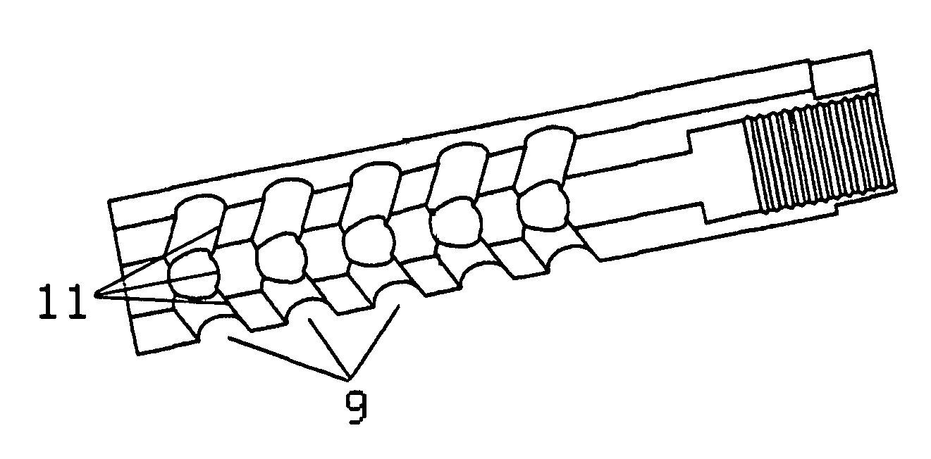
[0008]The embodiment of this invention, a Recoil, Sound and Flash Suppressor overcomes the present ineffectiveness in attached muzzle devices by using combustion gas thrust through the vents to effectively negate what escapes the muzzle while at the same time diminishing sound and flash through the unique geometry formed by the machining of said vent ports, which heretofore provides a sequential dispersant of the aforementioned gases.

Problems solved by technology

However, neither of those muzzle brakes direct the expulsion of combustion gas toward the breech, and neither creates the internal geometry to efficiently suppress sound and flash.

Method used


Image

  • Recoil, sound and flash suppressor
  • Recoil, sound and flash suppressor
  • Recoil, sound and flash suppressor

Examples


Embodiment Construction

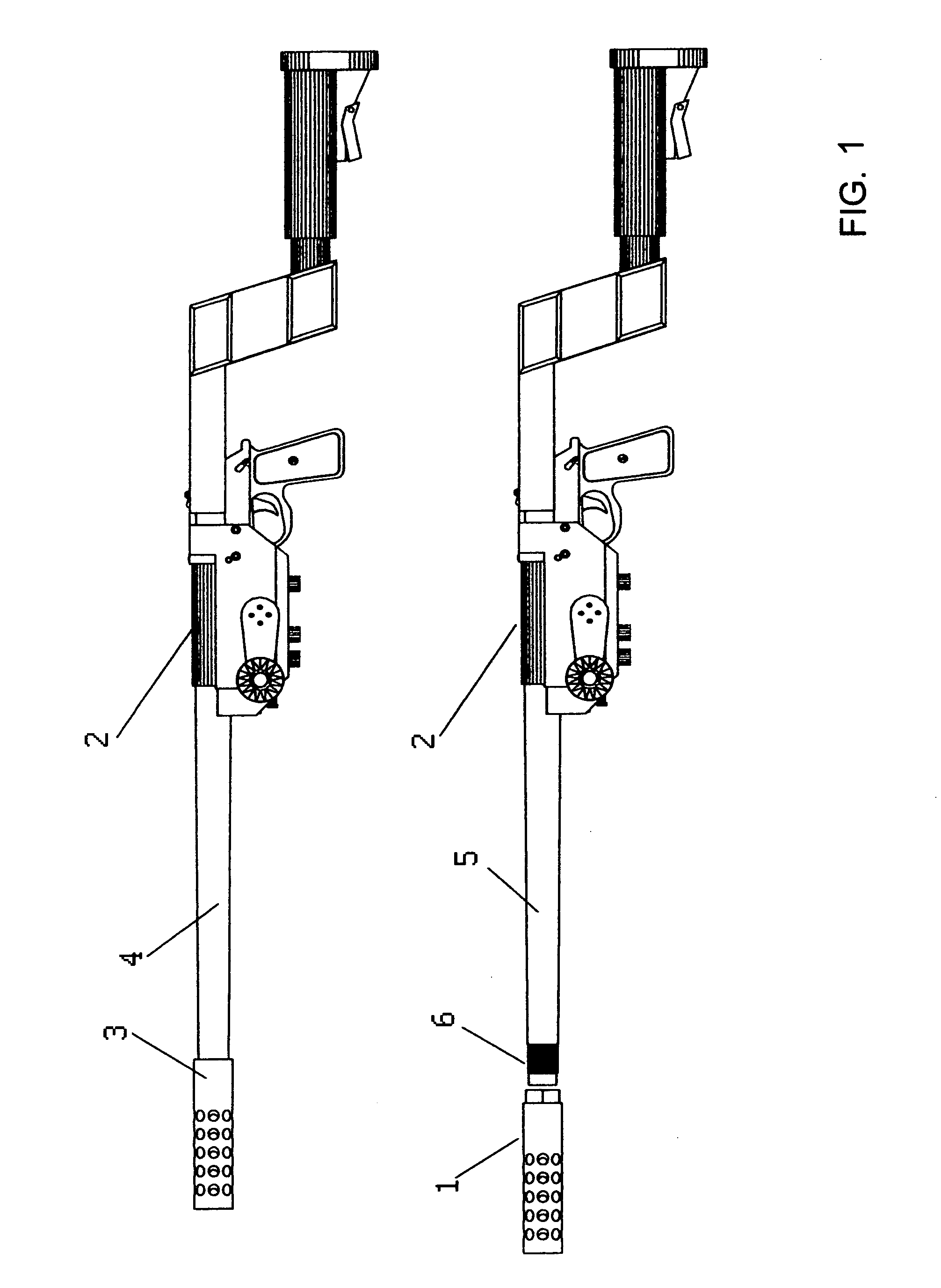
[0012]Referring to FIG. 1, the top illustration shows a large caliber rifle 2 with the fixed or permanent embodiment of the Recoil, Sound and Flash Suppressor 3 machined to the rifle barrel 4 as one part. The bottom illustration on FIG. 1 shows how the removable embodiment of the Recoil, Sound and Flash Suppressor 1 with internal threads machined in the end of it can be attached to rifle barrel 5 through the use of threads 6 machined on to the end of barrel 5.

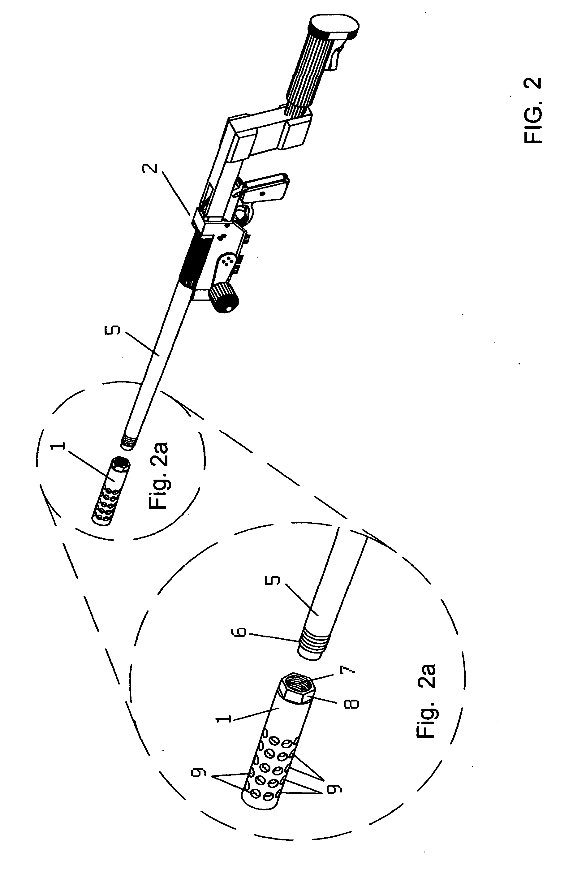
[0013]Referring to FIG. 2, the Recoil, Sound and Flash Suppressor 1 is attachable to rifle 2, or other firearm, with the use of internal threads 7 and hex area 8 which allows a wrench to tighten or loosen the removable Recoil, Sound and Flash Suppressor 1 and attach it to barrel 5 which has threads 6 machined on the end of it. Ports / holes 9 are machined to allow controlled escape of pressurized combustion gases from within the newly designed removable Recoil, Sound and Flash Suppressor 1 and the permanently attached Recoil, Sou...


PUM


Abstract

A Recoil, Sound and Flash Suppressor that is machined from a solid metal bar of a diameter determined by weapon caliber and mechanically attached to the end of said weapon's muzzle, with a series of gas ports radially machined to vent gas and create a unique scalloped chamber that is solely held integral by the outer body of said device to sequentially dissipate gas, sound and flash and negate most muzzle movement.

Description

CROSS REFERENCES TO RELATED APPLICATIONS[0001]Provisional Application for Patent No. 61 / 335,382 of 01610 with title “Recoil Suppressor” which is hereby incorporated by reference. Applicant claims priority pursuant to 35 U.S.C. Paragraph 119(c).[0002]U.S. Pat. No. 3,707,899 issued to Walter E. Perrine and U.S. Pat. No. 4,545,285 issued to Clifford E. McLain are the muzzle brake patents that come closest to the new invention. However, neither of those muzzle brakes direct the expulsion of combustion gas toward the breech, and neither creates the internal geometry to efficiently suppress sound and flash.COPYRIGHT NOTICE[0003]A portion of the disclosure of this patent document contains material which is subject to copyright protection. The copyright owner has no objection to the facsimile reproduction by anyone of the patent document or the patent disclosure, as it appears in the Patent and Trademark Office patent file or records, but otherwise reserves all copyright rights whatsoever.S...

Claims


Application Information

Patent Timeline
Patent Type & Authority Applications(United States)
IPC IPC(8): F41A21/36F41A21/34
CPCF41A21/30F41A21/36F41A21/34
Inventor ANTHONY, STEPHEN D.
Owner ANTHONY STEPHEN D
Learn More