
High-voltage protection circuitry in a data access arrangement

a high-voltage protection circuit and data access technology, applied in the field of communication devices, can solve the problems of diode bridge not adequately protecting the diode bridge fails, and the line side circuitry is affected, so as to achieve effective negation, successfully and economically withstand surge voltage, and effectively bypass the line side circuitry

Inactive Publication Date: 2005-04-05
SKYWORKS SOLUTIONS INC
View PDF4 Cites 23 Cited by
  • Summary
  • Abstract
  • Description
  • Claims
  • Application Information

AI Technical Summary

Benefits of technology

Briefly, a communication device implemented in accordance with the present invention utilizes a data access arrangement (DAA) having improved surge protection. The DAA incorporates a high voltage clamping device functioning to protect line side circuitry from signal paths created by EMI capacitors.
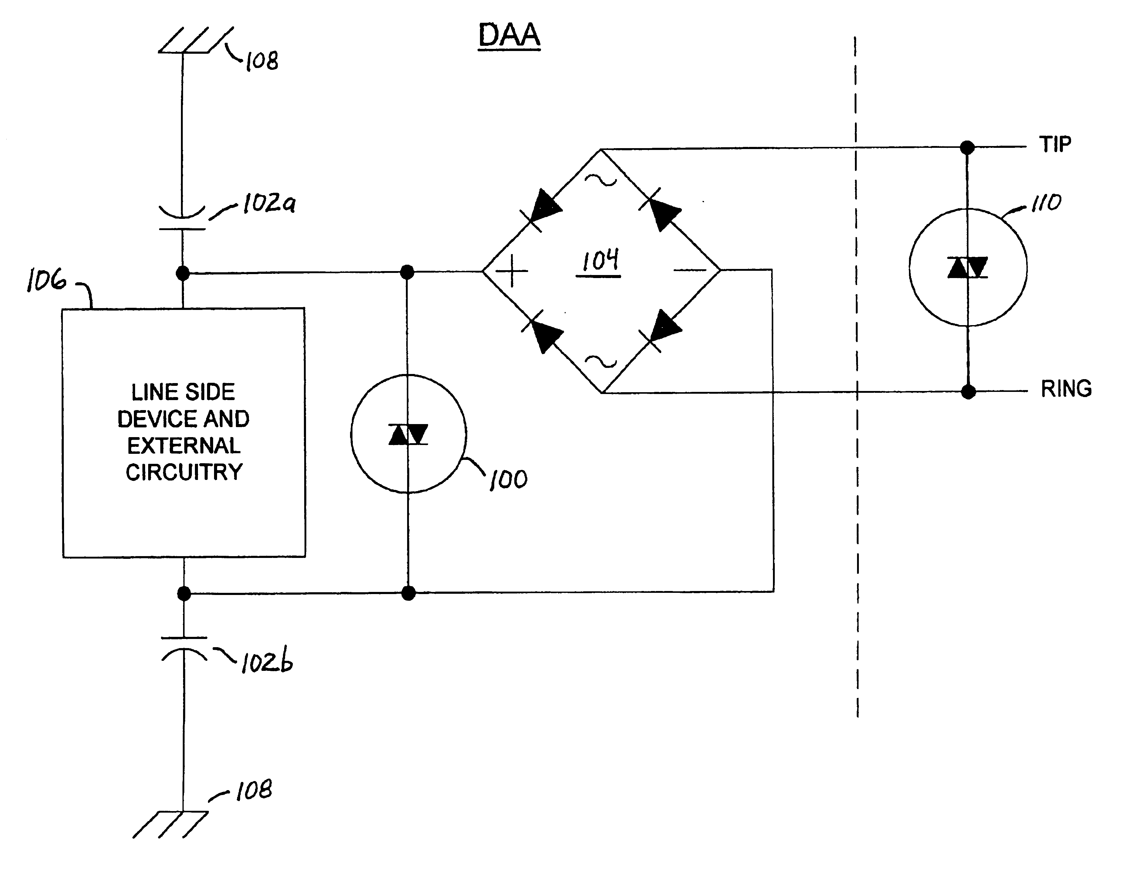
In one embodiment of the invention, EMI capacitors are added between the “plus” and “minus” terminals of the diode bridge and earth or chassis ground to balance and reduce noise injection onto the TIP and RING lines. These EMI capacitors also reduce EMI interference. However, by adding EMI capacitors on this side (the “rectified side” or “line side”) of the diode bridge, a high voltage signal path to earth ground is created that may have deleterious effects on the line side circuitry.
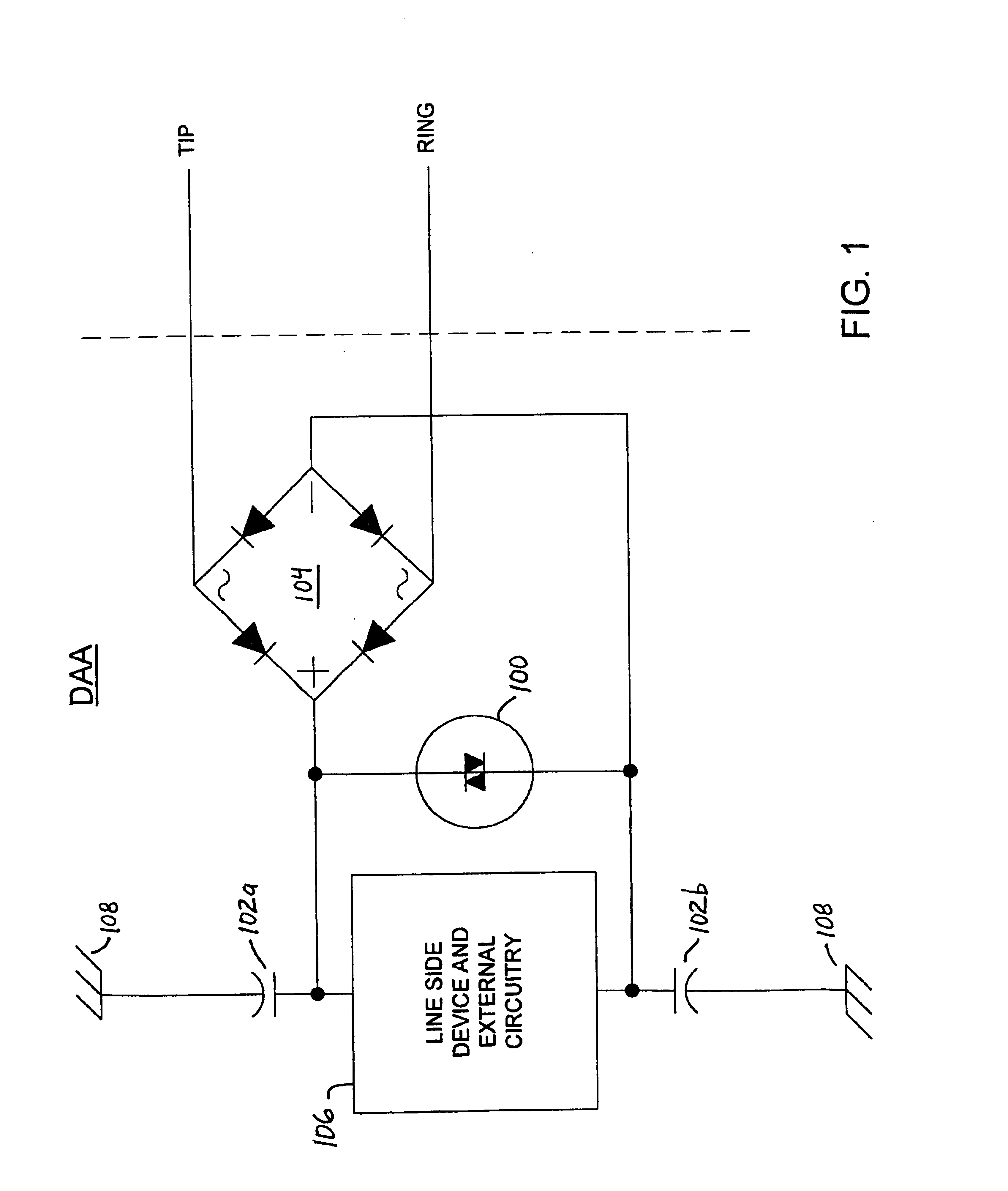
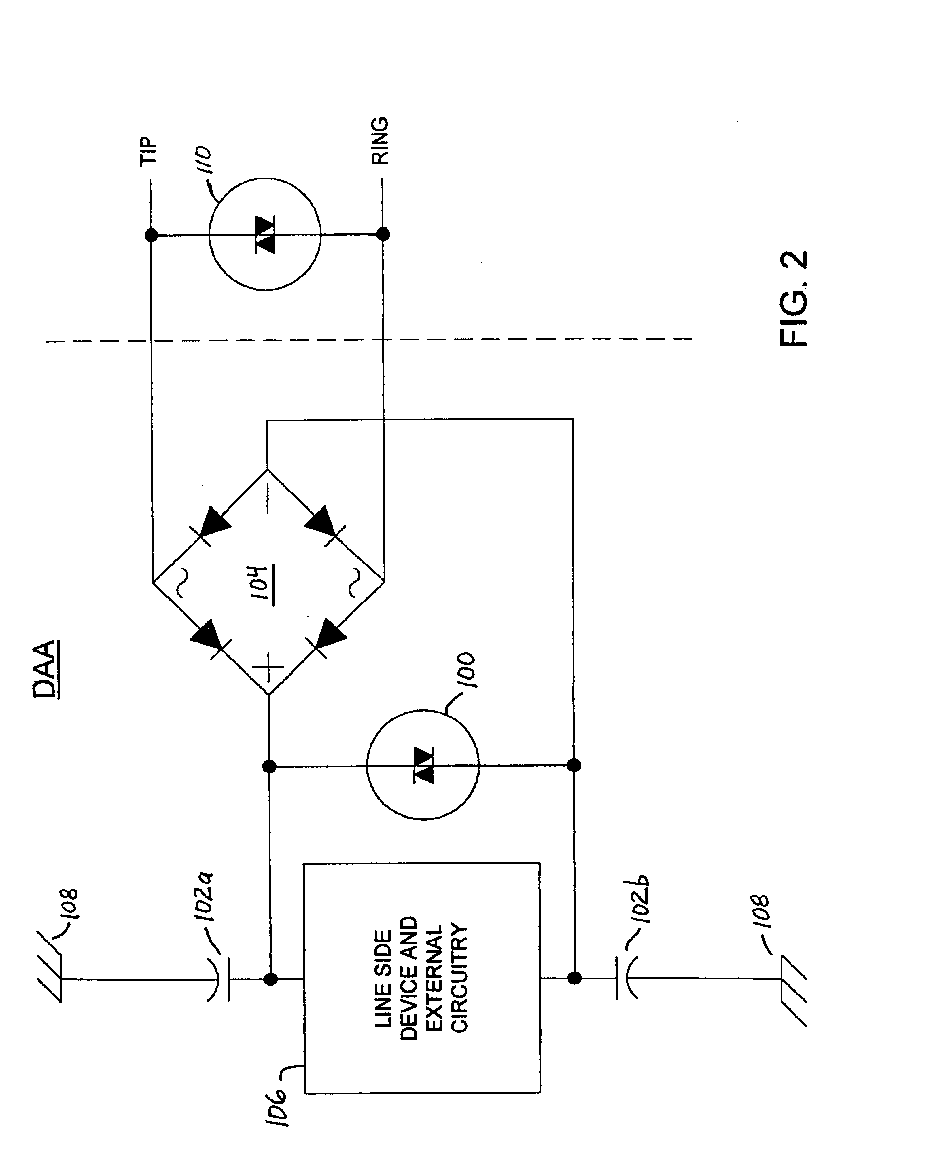
To effectively negate the undesirable signal path through the EMI capacitors to chassis ground, a DAA implemented in accordance with one embodiment of the present invention includes a high voltage clamping device (e.g., a MOV, SIDACTor™, gas discharge tube or similar device) disposed between the plus and minus terminals of the diode bridge for suppressing high voltage spikes. The high voltage clamping device limits the voltage seen by the line side circuitry as a result of high voltage longitudinal surges by providing a current path from the plus terminal to the minus terminal of the diode bridge, thereby effectively bypassing the line side circuitry. The present invention recognizes and takes advantage of the fact that the diodes of a typical diode bridge are capable of withstanding the peak currents associated with most voltage surges. The DAA is thus able to successfully and economically withstand surge voltages when EMI capacitors are added between the plus and minus terminals of the diode bridge to chassis ground, respectively.
Further a DAA according to the present invention has increased immunity to other problems that may be observed during high voltage transient tests. Even a metallic or horizontal surge, for example, may be accompanied by a longitudinal spike due to imperfections in the surge generator equipment. Again, such unexpected longitudinal spikes are suppressed by the disclosed DAA.

Problems solved by technology

However, by adding EMI capacitors on this side (the “rectified side” or “line side”) of the diode bridge, a high voltage signal path to earth ground is created that may have deleterious effects on the line side circuitry.
Since line side circuitry is characteristically rated to operate only below certain voltage levels, high voltage energy transients in the line side EMI capacitors during surge conditions may cause the line side circuitry to fail.
The typical placement of the MOV on the non-rectified side of the diode bridge does not adequately protect the line side circuitry connected to the rectified side of the diode bridge.

Method used


Image

  • High-voltage protection circuitry in a data access arrangement
  • High-voltage protection circuitry in a data access arrangement
  • High-voltage protection circuitry in a data access arrangement

Examples


Embodiment Construction

FIG. 1 is a schematic diagram of an exemplary data access arrangement (DAA) incorporating voltage surge protection circuitry in accordance with the present invention. In this embodiment of the invention, a high voltage clamping device 100 (e.g., a MOV, SIDACTor™, gas discharge tube or a similar device) is disposed between the plus and minus terminals of a diode bridge 104 for purposes of suppressing high voltage spikes across the line side circuitry. The high voltage clamping device limits the high voltage that may be seen across the line side circuitry as a result of a longitudinal surge applied to the DAA when EMI capacitors 102a and 102b are coupled between the plus and minus terminals of the diode bridge 104 and a chassis ground node, respectively. The high voltage clamping device also limits the effects of metallic surges applied to the DAA. The EMI capacitors 102a and 102b function to balance and reduce noise injection into the TIP and RING signal lines of a telephone connecti...


PUM


Abstract

A data access arrangement (DAA) having improved surge protection. The DAA incorporates a high voltage clamping device functioning to protect line side circuitry from signal paths created by EMI capacitors. In one embodiment of the invention, EMI capacitors are added between the “plus” and “minus” terminals of the diode bridge of the DAA to balance and reduce noise injection onto the TIP and RING lines. These EMI capacitors also reduce EMI interference. However, by adding EMI capacitors on this side (the “rectified side” or “line side”) of the diode bridge, a high voltage signal path to earth ground is created that may have deleterious effects on the line side circuitry. To effectively negate undesirable signal paths through the EMI capacitors, the DAA includes a high voltage clamping device (e.g., a MOV, SIDACTor™, gas discharge tube or similar device) disposed between the plus and minus terminals of the diode bridge for suppressing high voltage spikes. The high voltage clamping device limits the voltage seen by the line side circuitry as a result of high voltage longitudinal surges by providing a current path from the plus terminal to the minus terminal of the diode bridge, thereby effectively bypassing the line side circuitry. The present invention recognizes and takes advantage of the fact that the diodes of a typical diode bridge are capable of withstanding the peak currents associated with most voltage surges.

Description

BACKGROUND1. Technical FieldThe present invention relates generally to communication devices for coupling to an external communication medium; and, more particularly, it relates to a telephone line data access arrangement providing improved surge protection.2. Related ArtRegulatory agencies throughout the world have established standards and regulations for connecting subscriber equipment to telephone networks. These regulations are intended to prevent damage to the telephone network and mitigate interference with other equipment also connected to the network. The regulations, however, often present difficult design challenges.According to the applicable regulatory standards of various countries, electrical and electronic equipment imported to or sold in these countries must neither cause excessive electromagnetic interference (EMI) nor be unduly susceptible to it (EMS). Compliance is often demonstrated by performing electromagnetic compliance (EMC) tests to recognized standards. FC...

Claims


Application Information

Patent Timeline
Patent Type & Authority Patents(United States)
IPC IPC(8): H04M1/74H04M1/738H04M1/57
CPCH04M1/745H04M1/7385H04M1/573
Inventor SACCA, FRANK
Owner SKYWORKS SOLUTIONS INC
Learn More