Autonomous valve with temperature responsive device
a technology of autonomous valves and devices, which is applied in the direction of valve details, valve operating means/releasing devices, and fluid removal, etc., can solve the problems of short circuit between injection pressure and production, differential pressure dropping further, and negative effect on drainage process efficiency, so as to increase production rate and reduce the effect of drainage process efficiency
- Summary
- Abstract
- Description
- Claims
- Application Information
AI Technical Summary
Benefits of technology
Problems solved by technology
Method used
Image
Examples
first embodiment
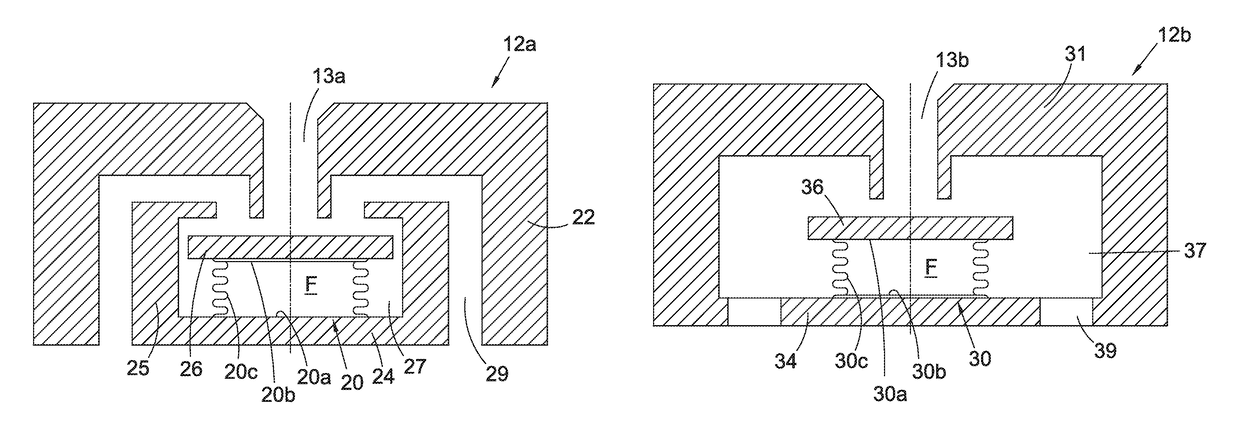
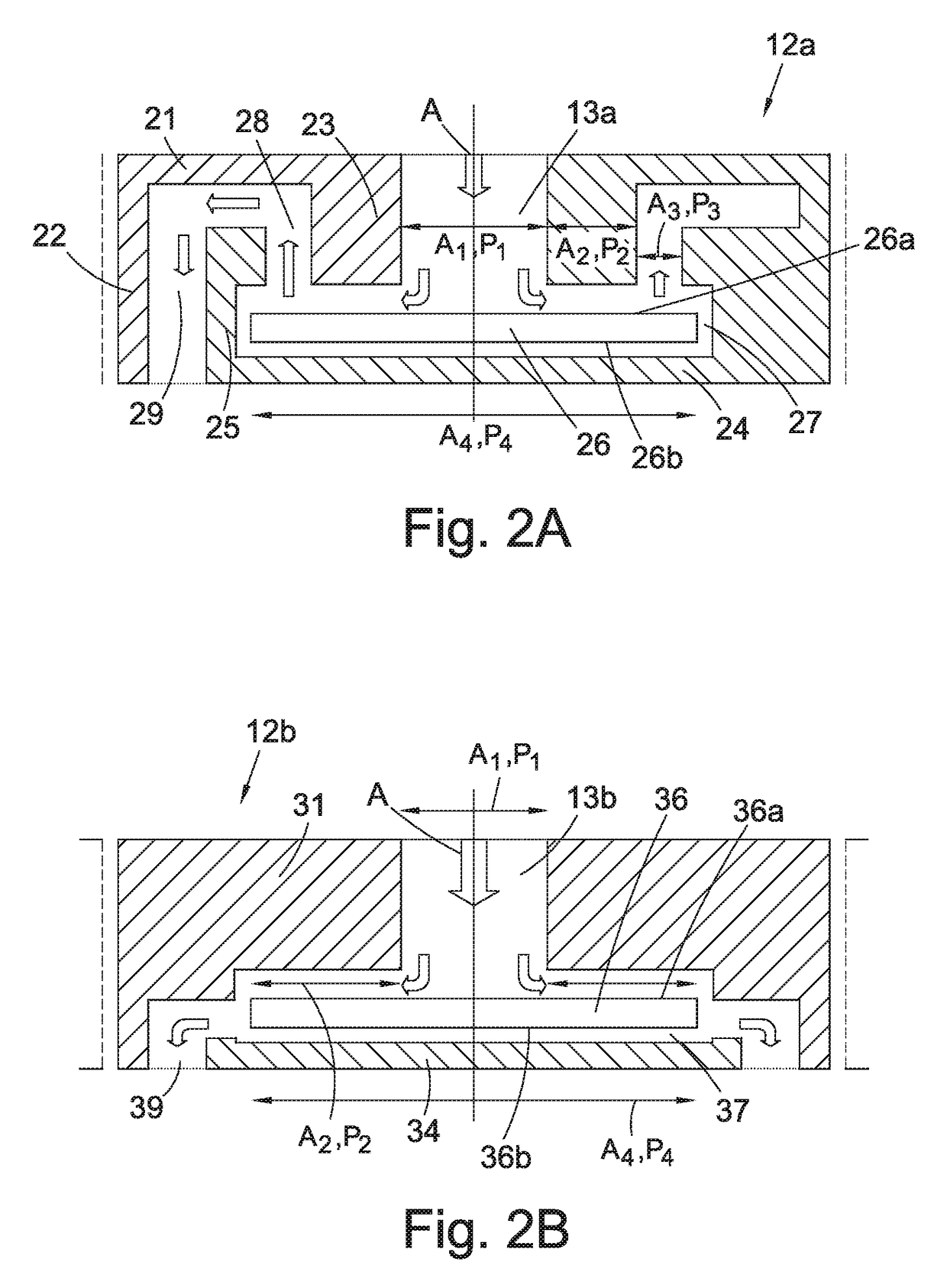
[0052]FIG. 3A shows a valve arrangement as shown in FIG. 2A provided with a heat expandable means according to the invention. For corresponding parts of the valve, the same reference numbers are used. According to this example, an expandable means in the form of a bellows 20 is arranged in a fluid chamber 27 in the valve, which chamber contains a movable valve body in the form of a disc 26 controlling the fluid flow through the valve. The position of the disc 26 is normally controlled by an inflow of fluid from an inlet port 13a located facing the centre of the disc 26 and flowing radially outwards over at least a portion of the disc 26 and towards an outlet port 29. In this example, the bellows 20 is located on the opposite side of the disc 26 relative to the fluid inlet port 13a. The bellows 20 comprises a first and a second substantially flat end surface 20a and 20b, which are connected by a corrugated section 20c. The sealed, expandable bellows 20 is at least partially filled wi...
second embodiment
[0055]FIG. 3B shows a valve arrangement as shown in FIG. 2B provided with a heat expandable means according to the invention. For corresponding parts of the valve, the same reference numbers are used. According to this example, an expandable means in the form of a bellows 30 is arranged in a fluid chamber 37 in the valve, which chamber contains a movable valve body in the form of a disc 36 controlling the fluid flow through the valve. The position of the disc 36 is normally controlled by an inflow of fluid from an inlet port 13a located facing the centre of the disc 36 and flowing radially outwards over at least a portion of the disc 36 and towards an outlet port 39. In this example, the bellows 30 is located on the opposite side of the disc 36 relative to the fluid inlet port 13a. The bellows 30 comprises a first and a second substantially flat end surface 30a and 30b, which are connected by a corrugated section 30c. The sealed, expandable bellows 30 is at least partially filled wi...
third embodiment
[0059]FIG. 4 shows a valve arrangement provided with a heat expandable means according to the invention. The valve arrangement is arranged to be mounted in a production line (not shown). According to this embodiment, a heat expandable means in the form of a bellows 40 is arranged in a fluid conduit 41, 42, 43 in series with the fluid flow through the valve arrangement. In this example, the bellows 40 is located in a housing 44 supplied by a first conduit 41 through which the entire fluid flow from the formation passes, before passing to a valve 45 to be controlled through a second conduit 42. The fluid flow leaves the valve 45 through a third conduit 43 and enters the production pipe. The bellows 40 is connected to a movable valve body 46 (schematically indicated) in order to act on said valve body to close the valve 45. When an increase of temperature in the fluid flowing through the housing 44 and the valve 45 occurs, heat is transferred by the hot fluid to a liquid inside the bel...
PUM
 Abstract
Description
Claims
Application Information
 - R&D
- Intellectual Property
- Life Sciences
- Materials
- Tech Scout
- Unparalleled Data Quality
- Higher Quality Content
- 60% Fewer Hallucinations
Browse by: Latest US Patents, China's latest patents, Technical Efficacy Thesaurus, Application Domain, Technology Topic, Popular Technical Reports.
© 2025 PatSnap. All rights reserved.Legal|Privacy policy|Modern Slavery Act Transparency Statement|Sitemap|About US| Contact US: help@patsnap.com


