
Fuel cell system with air-cooled compressor/turbine unit and method

a technology of compressor/turbine unit and fuel cell system, which is applied in the field of fuel cell system, can solve the problems of energy having a negative effect on the overall efficiency of electric machines, the loss of main mass flow of the cooling system, and the loss of mass flow of the fuel cell system, so as to improve the cooling of an air compressor

Pending Publication Date: 2022-08-04
ROBERT BOSCH GMBH
View PDF0 Cites 0 Cited by
  • Summary
  • Abstract
  • Description
  • Claims
  • Application Information

AI Technical Summary

Benefits of technology

The patent is about a fuel cell system that uses an air compressor to compress air for use in the fuel cell. The system also has a cooling air path for controlling the air temperature. The system has a controller that adjusts the cooling air mass flow based on factors like the rotational speed and power of the electric machine. This results in a more efficient fuel cell system. The controller uses a measuring point to detect the temperature of the cooling air and adjusts the mass flow based on the detected temperature. The cooling air path also has a bimetallic matrix that allows for precise control of the cooling air mass flow. This prevents unnecessary branching of air between the air compressor and fuel cell. Overall, the patent describes a system that provides better cooling control for a more efficient fuel cell system.

Problems solved by technology

The mass flow of the cooling system represents a loss in the main mass flow of the fuel cell system since the cooling air mass flow is no longer available in a stack of the fuel cell.
This energy has a negative effect on an overall efficiency of the electric machine.

Method used


Image

  • Fuel cell system with air-cooled compressor/turbine unit and method

Examples


Embodiment Construction

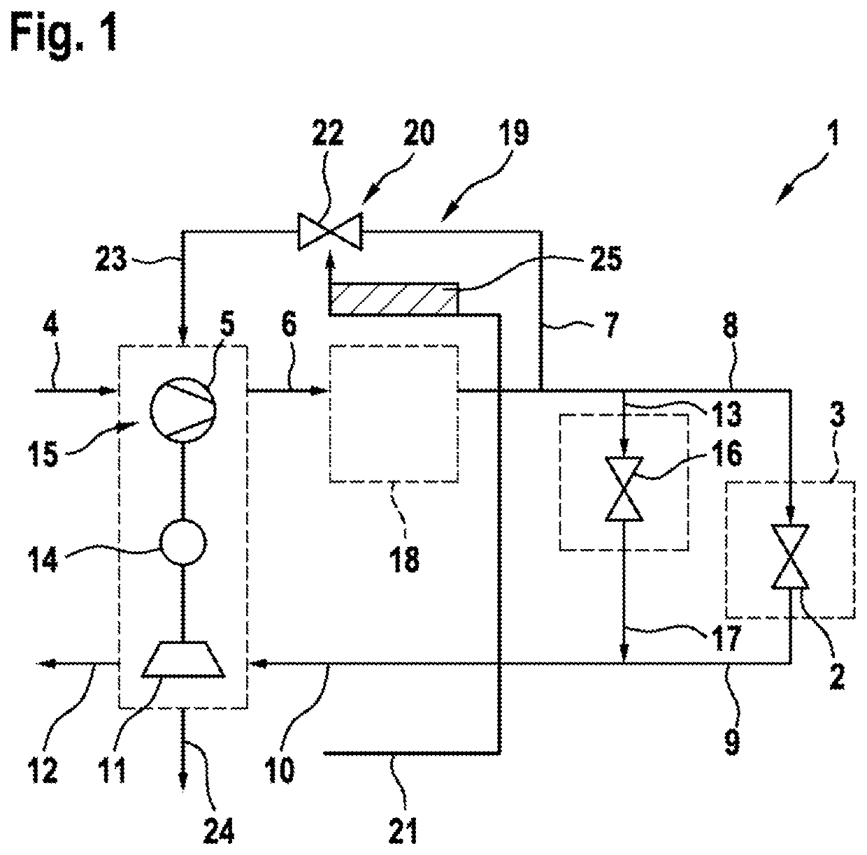
[0016]A fuel cell system 1 is illustrated schematically in FIG. 1.

[0017]Fuel cell systems are known per se, for example from German Laid-Open Application DE 10 2012 224 052 A1. The fuel cell system 1 comprises a fuel cell 3, which is indicated only by a rectangle in dashed lines. The fuel cell 3 comprises at least one stack 2, which is represented by an equivalent valve symbol.

[0018]An air mass flow, which is fed to the fuel cell 3 via an air compressor 5, is indicated by an arrow 4. An arrow 6 indicates a compressed air mass flow 6, from which a cooling air mass flow 7 is branched off. The cooling air mass flow 7 is likewise indicated only by an arrow and is part of a cooling air path 19, via which cooling air is fed to the air compressor 5.

[0019]The cooling air fed in via the cooling air path 19 serves, for example, to cool air bearings, by means of which a shaft of the air compressor 5 is rotatably mounted. The cooling air mass flow 7 represents a loss in the compressed air mass ...


PUM

PropertyMeasurementUnit
air mass flowaaaaaaaaaa
temperatureaaaaaaaaaa
outlet temperatureaaaaaaaaaa

Abstract

The invention relates to a fuel cell system (1) comprising an air compressor (5) which is used to compress an air mass flow (4) that is supplied to at least one fuel cell (3), and further comprising a cooling air path (19), via which a cooling air mass flow (7) is branched off from the compressed air mass flow (6). The cooling of the air compressor (5) in the fuel cell system (1) is further improved by an on-demand control (20) of the compressed cooling air mass flow (6).

Description

BACKGROUND OF THE INVENTION[0001]The invention relates to a fuel cell system having an air compressor which serves to compress an air mass flow that is fed to at least one fuel cell, and having a cooling air path, via which a cooling air mass flow is branched off from the compressed air mass flow. The invention also relates to a method for operating an air compressor in a fuel cell system of this kind.[0002]German Laid-Open Application DE 10 2017 212 815 A1 discloses a fuel cell system having a fuel cell, an air feed line for feeding an oxidizing agent into the fuel cell and an exhaust line for discharging the oxidizing agent from the fuel cell, wherein the fuel cell system has a turbomachine having an impeller, which is embodied as a compressor, which is arranged in the air feed line, wherein, in order to optimize the cooling of the turbomachine, it is not compressed air which has already been heated that is used by the impeller; instead, uncompressed air which has been cooled is s...

Claims


Application Information

Patent Timeline
Patent Type & Authority Applications(United States)
IPC IPC(8): H01M8/04014H01M8/04111H01M8/0432H01M8/04746
CPCH01M8/04014H01M8/04111H01M8/04373H01M2250/20H01M8/04768H01M8/04776H01M8/04358H01M8/0435Y02T90/40Y02E60/50
Inventor ZONDLER, JOHANNESOTT, TOBIAS REINHARD
Owner ROBERT BOSCH GMBH
Learn More