
Star sensor with reduced sensitivity to stray light induced by the sun or by other sources close to the field of view

a technology of star sensors and stray light, applied in the field of star sensors, can solve the problems of prohibitive light of the sun close to for instance 10° from the field of view, and the dimensions of the shielding baffle, so as to achieve more efficient blocking and reduce the minimum angle formed

Inactive Publication Date: 2012-10-04
GIULIANINI FAB
View PDF2 Cites 14 Cited by
  • Summary
  • Abstract
  • Description
  • Claims
  • Application Information

AI Technical Summary

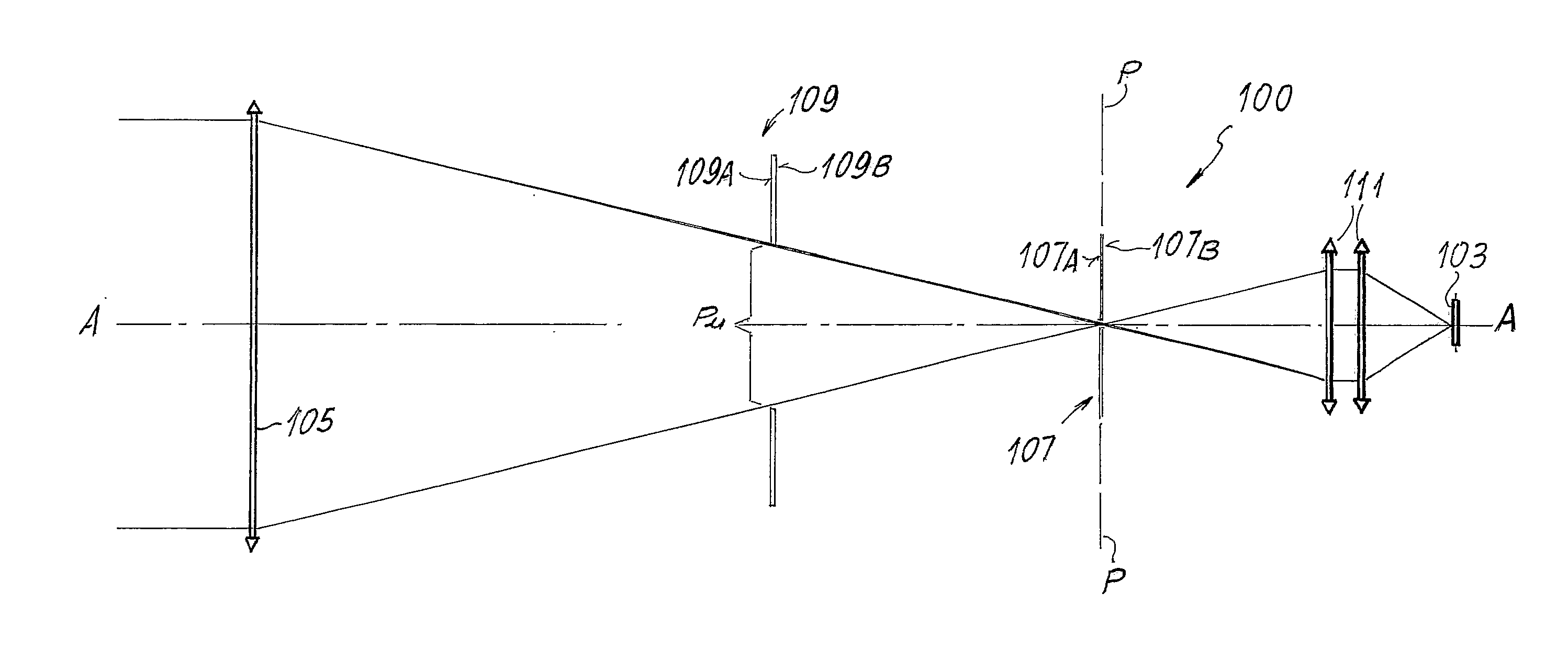
Benefits of technology

[0010]According to a particular aspect, the invention provides a star sensor or attitude sensor that enables more efficient blocking of the radiation emitted by the objects out of the field of view, reducing the minimum angle formed between the optical axis of the system and the source, the radiation of which is to be excluded from the field of view of the sensor.
[0012]Basically, contrary to what occurs in traditional attitude sensors or star sensors, according to one aspect of the invention the detector is not set directly in the focal plane of the objective but rather at a distance therefrom, and a field stop is positioned in the focal plane of the primary objective. This, in combination with the relay system for conveying the image, enables attenuation of the residual radiation diffused by the walls of the primary objective and by the absorbent-reflective stops set before the field stop that reaches the detector. These elements could otherwise illuminate by diffusion a detector set directly in the focal plane of the objective.
[0017]With a configuration according to the invention, it is possible to reach stray light-rejection angles larger by just a fraction of degree than the half-field of view. The source of stray light can thus even almost arrive at lapping the field of view of the sensor. Said result can be achieved even without the use of baffles or shadows and hence preventing the encumbrance, weight, and cost of said elements. The efficiency of the system in terms of stray light rejection can be slightly improved also using a baffle or shadow set in front of the objective; however said baffle can have dimensions substantially smaller than the ones used in traditional star sensors and which in any case cannot achieve the reduced values of the rejection angle that can be achieved with the optics of the star sensor of the present invention.

Problems solved by technology

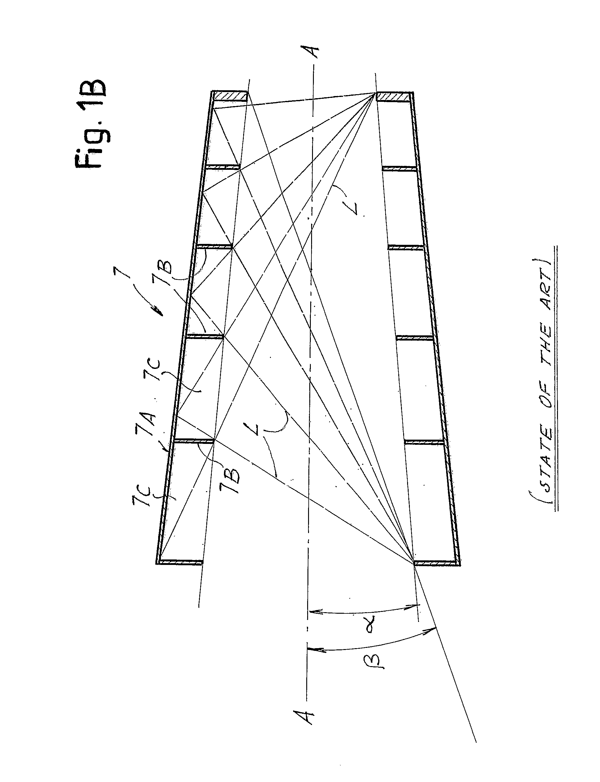
The dimensions of the baffles for shielding, for example, the light of the sun close to the field of view, for instance 10° from the field of view, become prohibitive.

Method used


Image

  • Star sensor with reduced sensitivity to stray light induced by the sun or by other sources close to the field of view
  • Star sensor with reduced sensitivity to stray light induced by the sun or by other sources close to the field of view
  • Star sensor with reduced sensitivity to stray light induced by the sun or by other sources close to the field of view

Examples


Embodiment Construction

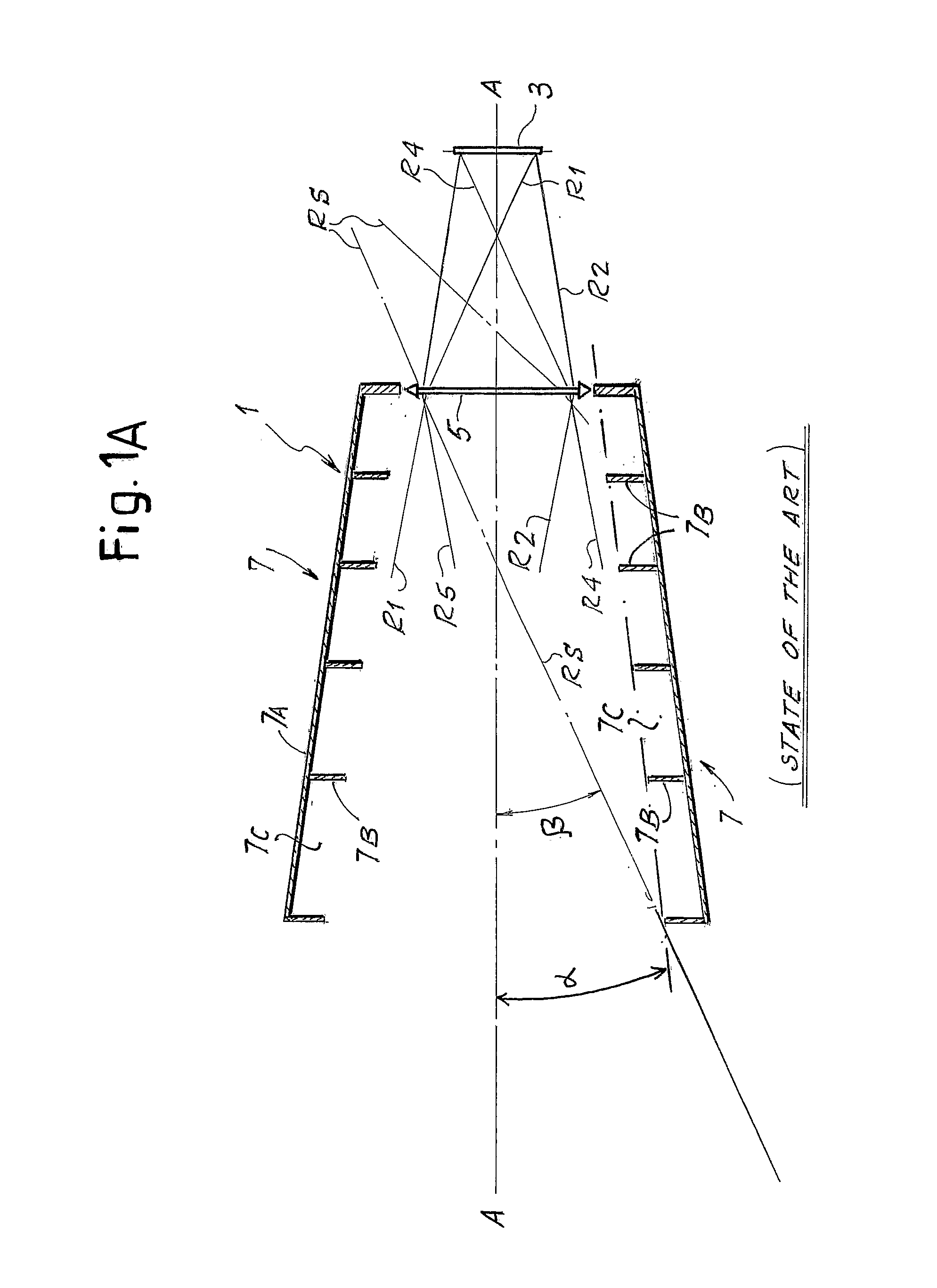
[0025]For a better understanding of the present invention, an optical system of a traditional sensor shown schematically in FIG. 1A will first be briefly described. The sensor, designated as a whole by 1, comprises an array detector 3, on which the image of a portion of the celestial vault is formed by means of a primary objective, constituted by a more or less complex optics, designated schematically herein by 5.

[0026]Set in front of the primary objective 5 is an external baffle or shadow 7, which has a particularly large length with respect to the dimension of the objective 5 and the detector 3. The function of the baffles 7 is to shield the objective 5 of the sensor 1, preventing the radiation of sources external to the field of view, for example light radiation coming from the sun, which would blind the detector 3 and thus jeopardize proper operation thereof, from reaching the detector 3 along the optical path.

[0027]Designated by A-A in the diagram of FIG. 1A is the optical axis...


PUM


Abstract

The sensor comprises a detector (103) and a primary objective (105) arranged in front of the detector to form on said detector images of stars present in the field of view of the sensor. Between the objective (105) and the detector (103) is arranged a field stop (107) positioned substantially in the focal plane (P) of the objective (105). Between the field stop (107) and the detector (103) is arranged a relay optics (111) for conveying an image from the focal plane of the objective to the detector.

Description

TECHNICAL FIELD[0001]The present invention relates to star sensors or so-called attitude sensors. These sensors are normally used in variable number on artificial satellites or other devices in general for space applications, for the purpose of controlling the attitude of the device or vehicle with respect to the celestial vault.STATE OF THE ART[0002]In order to control and possibly modify the attitude of a space vehicle, such as a satellite or the like, set on the vehicle itself are one or more star sensors, which detect an image of a portion of the celestial vault in order then to make the comparison of the image detected with stored stellar maps so as to verify, control, and possibly modify the attitude of the device or vehicle on which the sensor or sensors are set.[0003]Star sensors are constituted in general by an objective that forms on an array detector images of the stars present in the field of view of the objective itself. The recognition of the stars through stellar maps...

Claims


Application Information

Patent Timeline
IPC IPC(8): G01D5/26G01C21/02
CPCG01S3/7867G02B5/005G02B13/001G02B23/00
Inventor GIULIANINI, FABRIZIO
Owner GIULIANINI FAB
Learn More