
Stable light source device

a light source and stable technology, applied in semiconductor devices, electric lighting sources, electric light sources, etc., can solve the problems of difficult to provide consistent faint light amounts, difficult to distinguish light emission portions with small light amounts, and complicated operation

Active Publication Date: 2012-10-04
FUJIFILM CORP
View PDF4 Cites 32 Cited by
  • Summary
  • Abstract
  • Description
  • Claims
  • Application Information

AI Technical Summary

Benefits of technology

[0008]The present invention has been made to solve the problem described above, and the present invention provides a stable light source device that is provided with plural light emission portions differing in light amounts and that is capable of providing consistent faint light amounts.

Problems solved by technology

Therefore, to measure the dynamic range of a light detector, it is necessary to vary a light emission amount of the light source and perform imaging a plural number of times, and operation is complicated.
Moreover, although the light emission amount may be electronically varied to some extent, if light emission amounts are very different, it is difficult to provide consistent faint light amounts.
Although the respective light amounts of the plural light emission portions are different, if a light emission portion with a large light amount and a light emission portion with a small light amount are too close together, the light emission portion with the small light amount may be affected by light from the light emission portion with the large light amount, and it may not be possible to distinguish the light emission portion with the small light amount.
However, in regard to properties of the second integrating element, if the area of the apertures is excessively large, the incident light may not be uniformly diffused and reflected inside the second integrating element, and lights with uniform intensity distributions may not be provided.
The diameters of the light emission portions can be set to less than 3 mm but, if they are too small, light emission portions with small light emission amounts will, for example, be confused with image noise or the like and be hard to distinguish.

Method used


Image

  • Stable light source device
  • Stable light source device
  • Stable light source device

Examples


second exemplary embodiment

[0096]Next, a second exemplary embodiment of the stable light source device of the present invention is described in accordance with FIG. 7. Structures that are the same as in the first exemplary embodiment are assigned the same reference numerals and are not described.

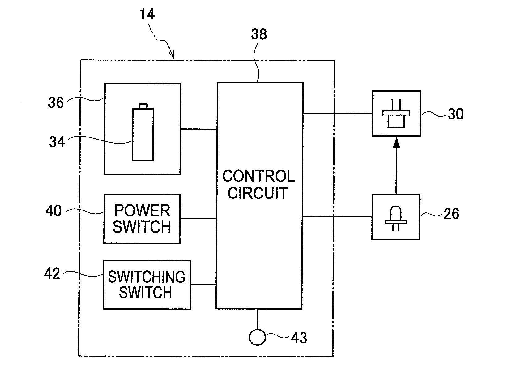
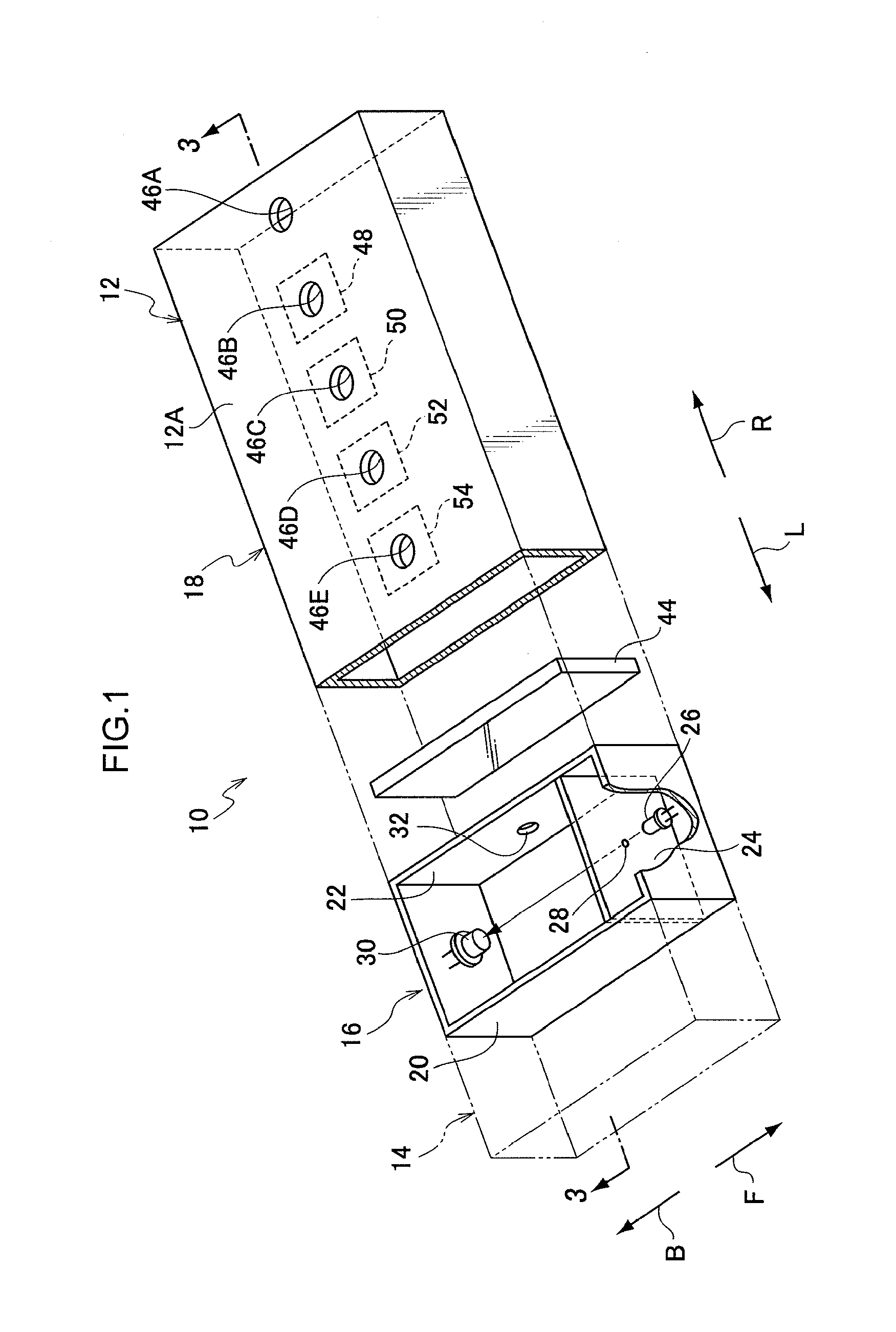
[0097]As illustrated in FIG. 7, the stable light source device 10 of the present exemplary embodiment has a structure in which two of the black box 12 described for the stable light source device 10 of the first exemplary embodiment are arranged in parallel and made integral. An LED 26B and an LED 26G are used. The LED 26B is provided in the black box 12 at the arrow B direction side and emits blue light (for example, with wavelength 470 nm), and the LED 26G is provided in the black box 12 at the arrow F direction side and emits green light (for example, with wavelength 530 nm).

[0098]Thus, if the stable light source device 10 of the present exemplary embodiment is used, green light emission and blue light emission may...


PUM


Abstract

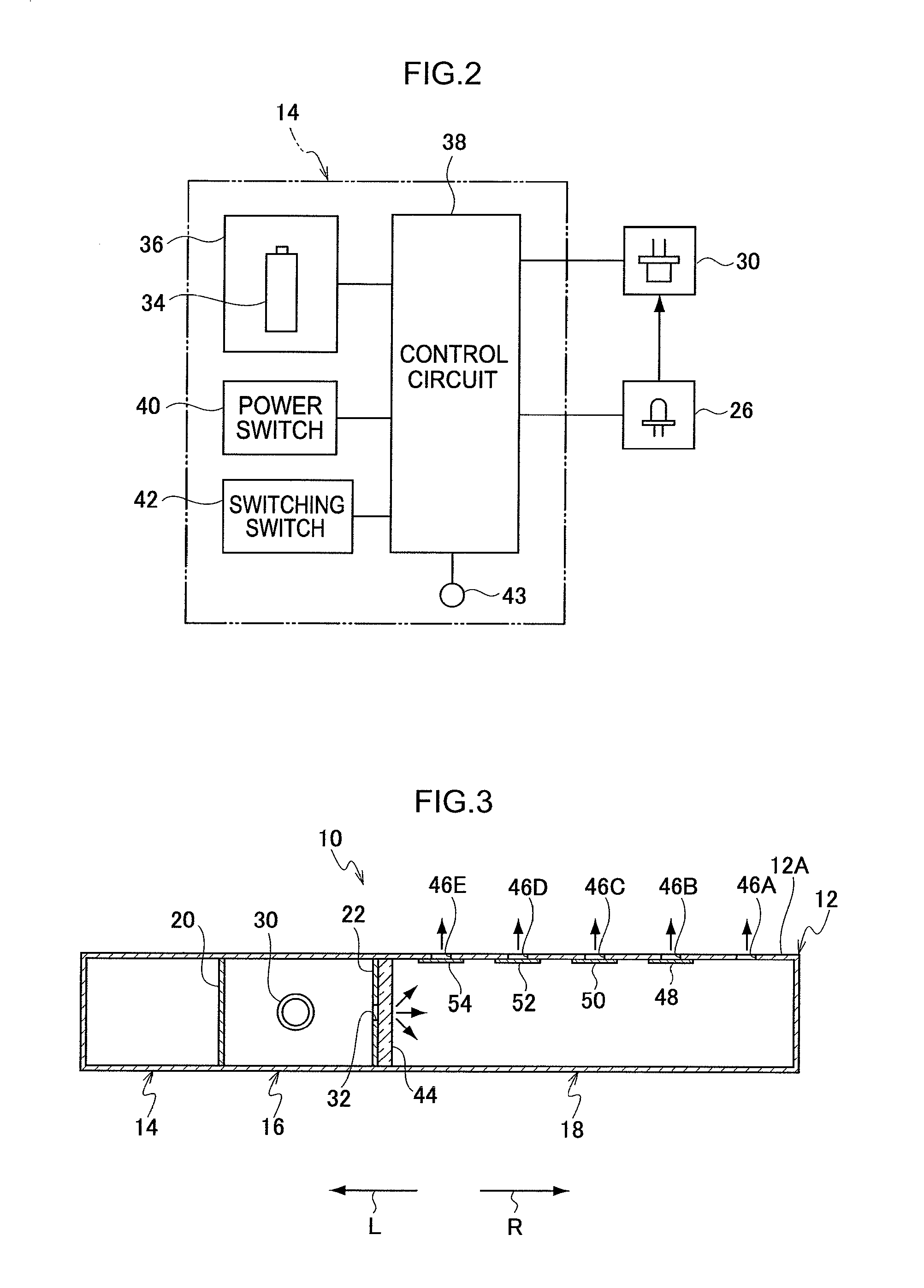
A stable light source device is provided with a light source, a pinhole constricting optical flux emitted from the light source, a first integrating element inside which optical flux from the pinhole is multiply reflected, a light detection sensor monitoring a light amount, a control section controlling the light source on the basis of the light amount monitored by the light detection sensor and making the light amount consistent, an aperture formed in the first integrating element and emitting light outside the first integrating element, a diffusion-transmission member disposed at a light emission side of the aperture, a branching section disposed at a light emission side of the diffusion-transmission member and branching incident light towards plural light emission portions, and neutral density filters provided at the light emission portions, transmitted light amounts thereof respectively differing such that light amounts at the light emission portions are respectively different.

Description

CROSS-REFERENCE TO RELATED APPLICATION[0001]This application claims priority under 35 USC 119 from Japanese Patent Application No. 2011-076618, filed Mar. 30, 2011, the disclosure of which is incorporated by reference herein.BACKGROUND[0002]1. Technical Field[0003]The present invention relates to a stable light source device that is used in checking and correcting sensitivity, locality and the like of a light detector, particularly an area sensor, for measuring faint light that is not visible to the naked eye such as bioluminescence, chemoluminescence or the like.[0004]2. Related Art[0005]A stable light source device that is used in checking and correcting sensitivity, locality and the like of a light detector, particularly an area sensor, for measuring faint light that is not visible to the naked eye, such as bioluminescence, chemoluminescence or the like, is disposed in an imaging region of an area sensor, and faint light emitted from the stable light source device is detected by ...

Claims


Application Information

Patent Timeline
Patent Type & Authority Applications(United States)
IPC IPC(8): H05B37/02
CPCH01L31/02019H01L31/147Y02B20/46H05B37/0218H05B33/0854H05B47/11Y02B20/40H05B45/12
Inventor IKAMI, SEISHI
Owner FUJIFILM CORP
Learn More