
Method and apparatus for light intensity control

a technology of light intensity control and light intensity, applied in the field of illumination systems, can solve the problems of reducing the accuracy of light information collected by the photosensor, unsatisfactory effects, and prone to optical crosstalk of the photosensor,

Inactive Publication Date: 2009-07-30
KONINKLIJKE PHILIPS ELECTRONICS NV
View PDF22 Cites 87 Cited by
  • Summary
  • Abstract
  • Description
  • Claims
  • Application Information

AI Technical Summary

Benefits of technology

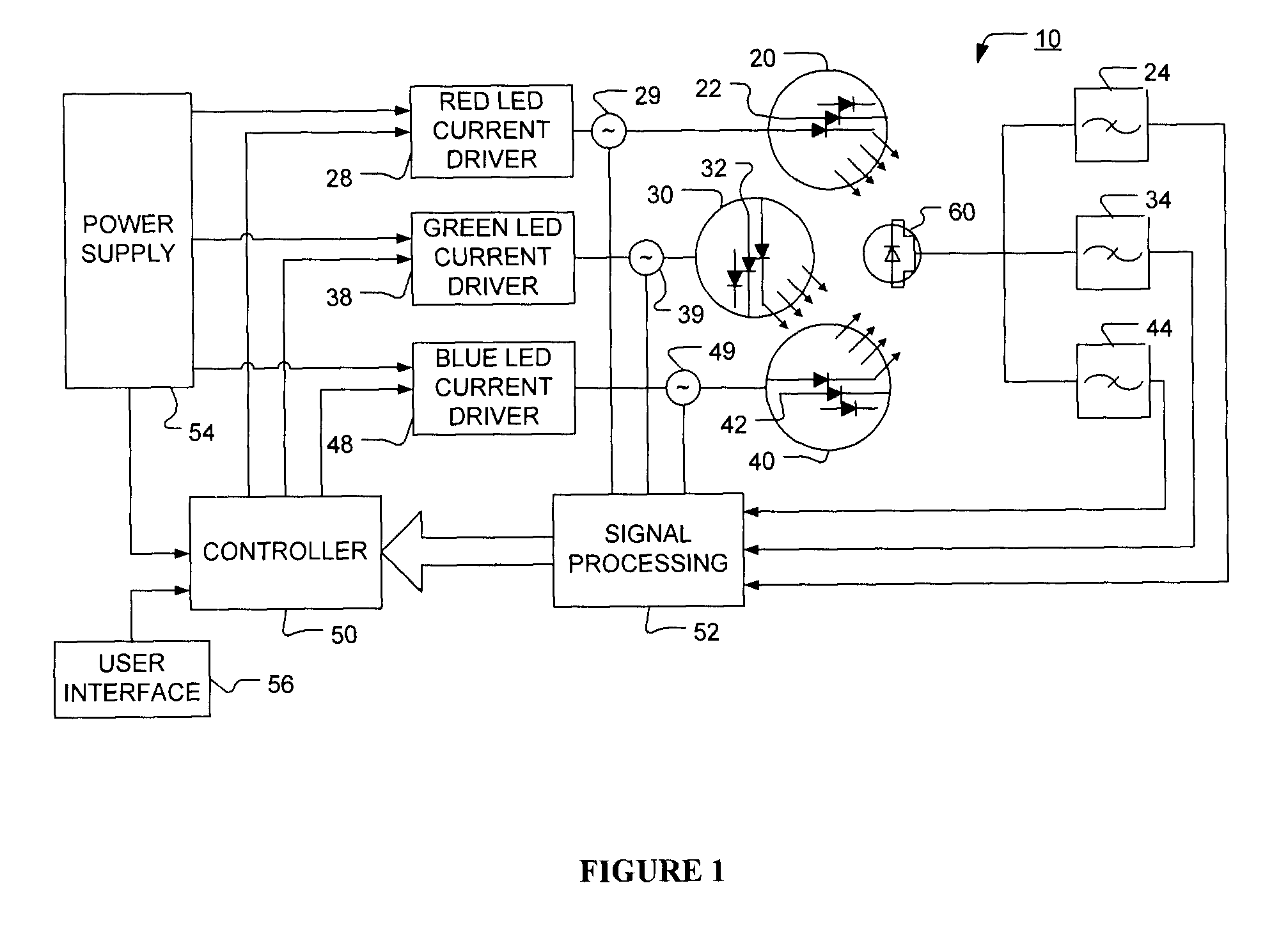
The present invention provides a method and apparatus for controlling the intensity and chromaticity of light. The apparatus includes one or more light-emitting elements, a current driver, and an optical sensor. The controller generates control signals for the current drivers based on an optical signal that represents the mixed radiant flux of the output light. The method involves adjusting the current drivers to achieve the desired luminous flux and chromaticity. The technical effect of the invention is to provide a more precise and accurate method for controlling the output light of a lighting device.

Problems solved by technology

These variations can cause undesirable effects under operating conditions of the LEDs.
These photosensors however, are prone to optical crosstalk due to the overlap in the spectral radiant power distribution of the light emitted by various colours of LEDs.
This optical crosstalk can reduce the accuracy of the light information collected by the photosensors.
Since the spectral radiant power distributions of the LEDs tend to overlap for the different colours, channel crosstalk is inevitable and can limit the performance of the optical feedback system.
Although satisfactory performance levels for such filters can be achieved using multilayer interference filters, these interference filters can be expensive and typically require further optics for collimating the emitted light, as the interference filter characteristics depend on the incidence angle at which the light impinges on these filters.
Another problem associated with interference filters is that the center wavelength of an LED depends on the LED junction temperature and this center wavelength can vary significantly depending on the type of LED.
Hence there exist situations where the output signal of the photosensor may change with ambient temperature even if the LED spectral radiant power distribution remains constant, which can further limit the performance of the sensor system.
A problem with this approach is that colour balance is periodically and potentially drastically altered each time the LEDs are de-energized, thereby possibly causing noticeable flicker.
Since the optical sensor requires a minimum amount of time to sense the radiant flux of the energized LEDs accurately and with an acceptable signal-to-noise ratio, the choice of sampling frequencies can be limited by the sensitivity and noise characteristics of the optical sensor.
A limited sampling frequency can result in lower sampling resolution and longer response times for the optical feedback loop.
Neither of these proposed solutions, however, addresses periodic and potentially drastic changes in colour balance or degradation in feedback loop response time due to the deactivation sequences required for light sampling.
A difficulty associated with this approach can be that the PWM pulses must be synchronized such that at least one LED colour is de-energized for a finite period of time during the PWM period.
Another disadvantage associated with the average light sensing method is that the sampling period typically must provide sufficient time for the optical sensor to reliably measure the radiant flux of the energized LEDs.
In addition this light sensing method requires that the LED colours are to be measured sequentially, which can limit the feedback loop response time.

Method used


Image

  • Method and apparatus for light intensity control
  • Method and apparatus for light intensity control
  • Method and apparatus for light intensity control

Examples


Embodiment Construction

Definitions

[0023]The term “light-emitting element” (LEE) is used to define any device that emits radiation in any region or combination of regions of the electromagnetic spectrum for example, the visible region, infrared and / or ultraviolet region, when activated by applying a potential difference across it or passing a current through it, for example. Therefore a light-emitting element can have monochromatic, quasi-monochromatic, polychromatic or broadband spectral emission characteristics. Examples of light-emitting elements include semiconductor, organic, or polymer / polymeric light-emitting diodes, blue or UV pumped phosphor coated light-emitting diodes, optically pumped nanocrystal light-emitting diodes or other similar devices as would be readily understood by a worker skilled in the art. Furthermore, the term light-emitting element is used to define the specific device that emits the radiation, for example a LED die, and can equally be used to define a combination of the specif...


PUM


Abstract

The present invention provides a method and apparatus for optical feedback control for an illumination device, wherein the control signal for each array of one or more light-emitting elements corresponding to a particular colour, is independently configured using a modification signal whose frequency is different for each colour. Electronic filters whose center frequencies are substantially equal to the modification signal frequencies of the drive currents for the light-emitting elements are used to discriminate between the radiant flux corresponding to each of the different colours of light-emitting elements, from a sample of the mixed radiant flux output collected by one or more optical sensors. The output of an individual electronic filter is substantially directly proportional to the radiant flux output of the light-emitting elements of the associated colour, which together with the desired luminous flux and chromaticity of the output light, the controller can use to adjust the control signals.

Description

FIELD OF THE INVENTION[0001]The present invention pertains to illumination systems and more particularly to a light intensity control method and apparatus for illumination systems.BACKGROUND[0002]Light-emitting diodes (LEDs) are semiconductor devices that convert electrical energy into electromagnetic radiation, including visible light. Due to their reliability, high luminous efficacy and low maintenance requirements, LEDs are increasingly being used in various lighting applications such as ambient lighting, signage, advertising, display lighting, and backlit lighting applications.[0003]It is well known that light of a desired spectral composition or, in photometric terms, a desired chromaticity and luminous flux, can be generated by intermixing adequate amounts of light from different colour light sources. When light from, for example, different colour LEDs is intermixed, the chromaticity of the mixed light can be sufficiently accurately determined by characteristics such as the in...

Claims


Application Information

Patent Timeline
Patent Type & Authority Applications(United States)
IPC IPC(8): H05B37/02H05B44/00
CPCH05B33/0869H05B33/0818H05B45/22
Inventor ASHDOWN, IANLOVELAND, DAMIENSPEIER, INGO
Owner KONINKLIJKE PHILIPS ELECTRONICS NV
Learn More