Apparatus and methods of operation of passive LED lighting equipment

Active Publication Date: 2010-10-28
CITY UNIVERSITY OF HONG KONG
View PDF17 Cites 91 Cited by
  • Summary
  • Abstract
  • Description
  • Claims
  • Application Information

AI Technical Summary

Benefits of technology

[0027]In another embodiment, instead of using a valley-fill circuit, an output capacitor connected across the rectified DC power is used to reduce the voltage ripple of the rectified DC power.
[0028]Preferably, the AC input voltage can be varied so that the LED lighting system is dimmable. This can be done by using a variable inductor in place of the input inductor described above. The use of a variable inductor may solely be for providing a dimming function, or may be for reducing the sensitivity of the LED power to fluctuations in the AC input supply in combination with providing a dimming function.
[0029]Controlling and reducing the sensitivity of the LED power to fluctuations in the AC input supply voltage can also be useful independently. Therefore, another aspect of the invention provides a method of providing power to a LED lighting system comprising the steps of: (a) providing an AC input; (b) reducing the sensitivity of the power provided to the LED lighting

Problems solved by technology

However, the electrolytic capacitors used in the power circuit and the electronic controls for LED systems have a limited lifetime, typically 15000 hours (or 1.7 years) at an operating temperature of 105° C. The lifetime of an electrolytic capacitor is highly sensitive to the operating temperature.
The lifetime is doubled if the operating temperature is decreased by 10° C. and halved if increased by 10° C. Therefore, the short lifetime of electronic control circuits (sometimes known as ball

Method used


Image

  • Apparatus and methods of operation of passive LED lighting equipment
  • Apparatus and methods of operation of passive LED lighting equipment
  • Apparatus and methods of operation of passive LED lighting equipment

Examples


Embodiment Construction

[0086]One important aspect of this invention at least in its preferred forms is to provide a way to reduce the size of the capacitors that is needed so that capacitors other than the electrolytic type can be used. With electrolytic capacitors eliminated in the lighting system, the whole system can be more reliable and last longer.

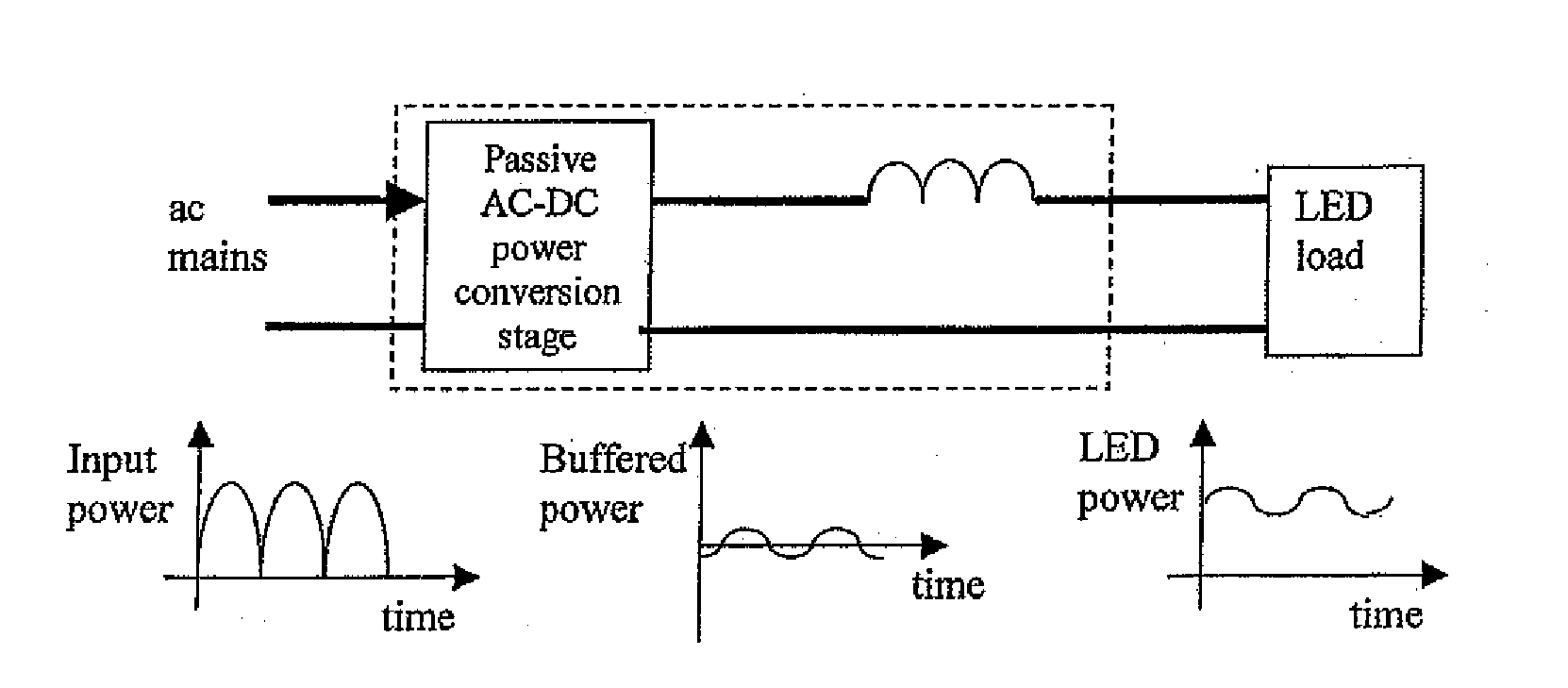
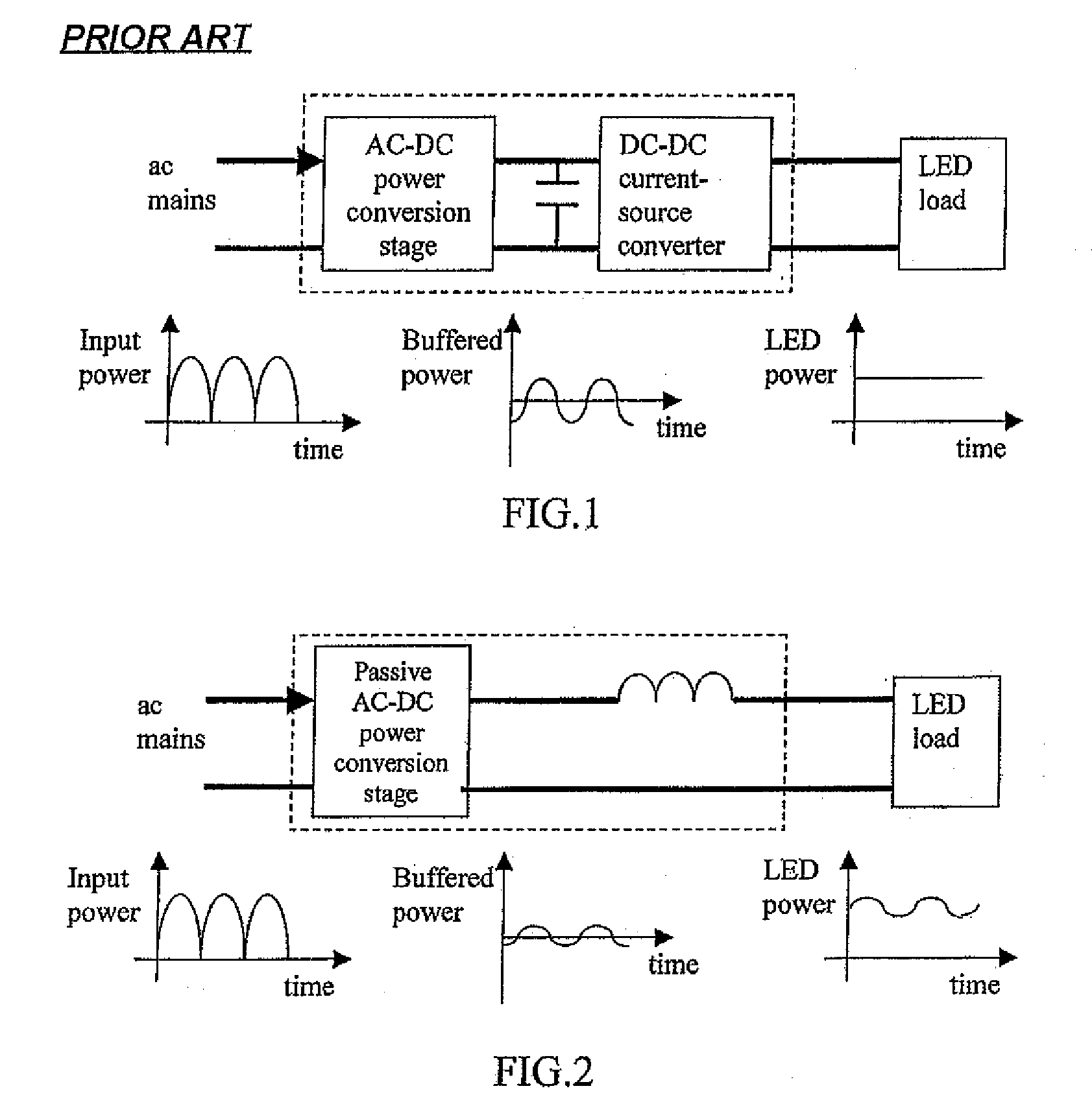
[0087]FIG. 2 is a modified version of FIG. 1 and is used to illustrate this aspect of the invention. If the LED load power is allowed to fluctuate to some extent, the amount of energy buffer required in the energy-storage element of the system becomes less and therefore the size of the capacitance can be reduced to a level that other non-electrolytic capacitors can be used to replace the electrolytic capacitor. Furthermore as the circuit contains only passive components rather than active components complicated control circuitry (which may also require electrolytic capacitors) can be avoided.

[0088]In addition to the elimination of electrolytic capacitors, t...


PUM


Abstract

This invention is concerned with the control and design of a LED lighting system that does not need electrolytic capacitors in the entire system and can generate light output with reduced luminous flux fluctuation. The proposal is particularly suitable, but not restricted to, off-line applications in which the lighting system is powered by the ac mains. By eliminating electrolytic capacitors which have a limited lifetime of typically 15000 hours, the proposed system can be developed with passive and robust electrical components such as inductor and diode circuits, and it features long lifetime, low maintenance cost, robustness against extreme temperature variations and good power factor. No extra electronic control board is needed for the proposed passive circuits, which can become dimmable systems if the ac input voltage can be adjusted by external means.

Description

CROSS-REFERENCE TO RELATED APPLICATIONS[0001]This application is a continuation-in-part of U.S. patent application Ser. No. 12 / 544,545, filed Aug. 20, 2009, which is a continuation-in-part of U.S. patent application Ser. No. 12 / 474,001, filed May 28, 2009, which is a continuation-in-part of U.S. patent application Ser. No. 12 / 429,792, filed Apr. 24, 2009, each of which is hereby incorporated herein by reference in its entirety.FIELD OF THE INVENTION[0002]This invention relates to apparatus and methods for the operation of passive light emitting diode (LED) lighting equipment, and in particular to such apparatus and methods as may avoid the need to use electrolytic capacitors.BACKGROUND OF THE INVENTION[0003]LED technology has been promoted as a promising lighting technology to replace energy-inefficient incandescent lamps and mercury-based linear and compact fluorescent lamps. It is often claimed by LED manufacturers that the LED devices have a long lifetime that could be higher tha...

Claims


Application Information

Patent Timeline
IPC IPC(8): H05B37/02H05B44/00
CPCY02B20/342H05B33/0809H05B45/355H05B45/375Y02B20/30
Inventor HUI, RON SHU YUENCHEN, WU
Owner CITY UNIVERSITY OF HONG KONG
Why Eureka
Try Eureka