Optical device and projector

a technology of optical devices and projectors, applied in the direction of projectors, instruments, mountings, etc., can solve the problems of increasing the calorific value per unit volume, the inability to realize sufficient radiation of cooling with gas, and the difficulty of sufficiently cooling the polarizer

Inactive Publication Date: 2007-09-06
COLUMBIA PEAK VENTURES LLC
View PDF2 Cites 87 Cited by
  • Summary
  • Abstract
  • Description
  • Claims
  • Application Information

AI Technical Summary

Benefits of technology

[0011]An advantage of some aspects of the invention is to provide an optical device and a projector in which entry of dust or the like into the refrigerant that cools the light modulation element is prevented and in which the entire device is miniaturized.

Problems solved by technology

However, as the density of semiconductors becomes higher, the calorific value per unit volume increases and the cooling with a gas cannot realize sufficient radiation.
That is, in the projector disclosed in JP-A-2003-195253, since the polarizer is cooled by using free convection, it is difficult to sufficiently cool the polarizer.
Also, the refrigerant may leak from the connecting parts of the fluid circulation n embers and dust may enter the fluid circulation members because of the connection of the fluid circulation members.
Also, since three liquid crystal panels are arranged within one cooling container, assembly of the liquid crystal display device is difficult.
Maintenance is difficult when one of the liquid crystal panels has trouble, and the other liquid crystal panels may also have trouble.

Method used


Image

  • Optical device and projector
  • Optical device and projector
  • Optical device and projector

Examples


first embodiment

[0054]An optical device according to a first embodiment of the invention will be described with reference to FIGS. 1 to 5.

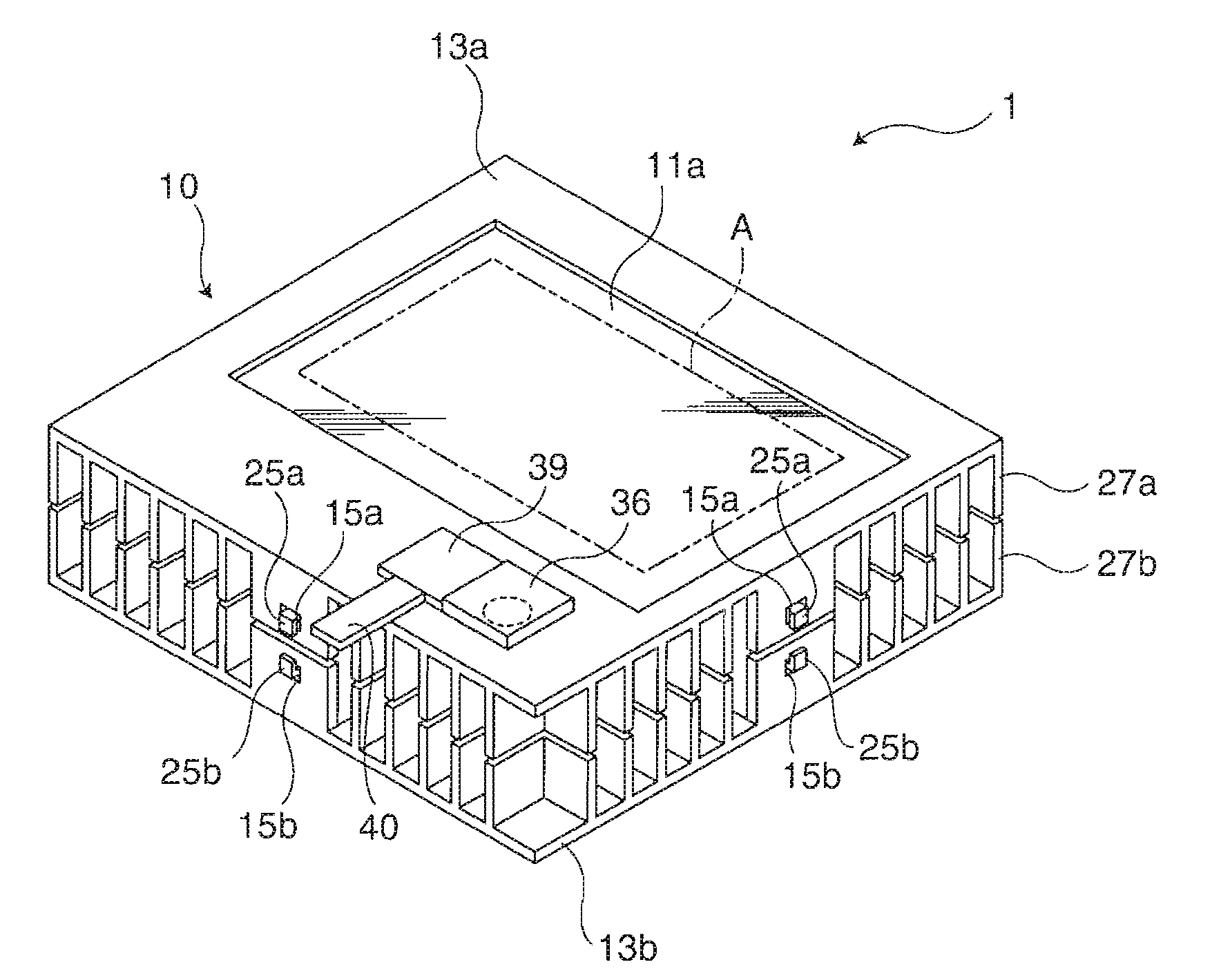
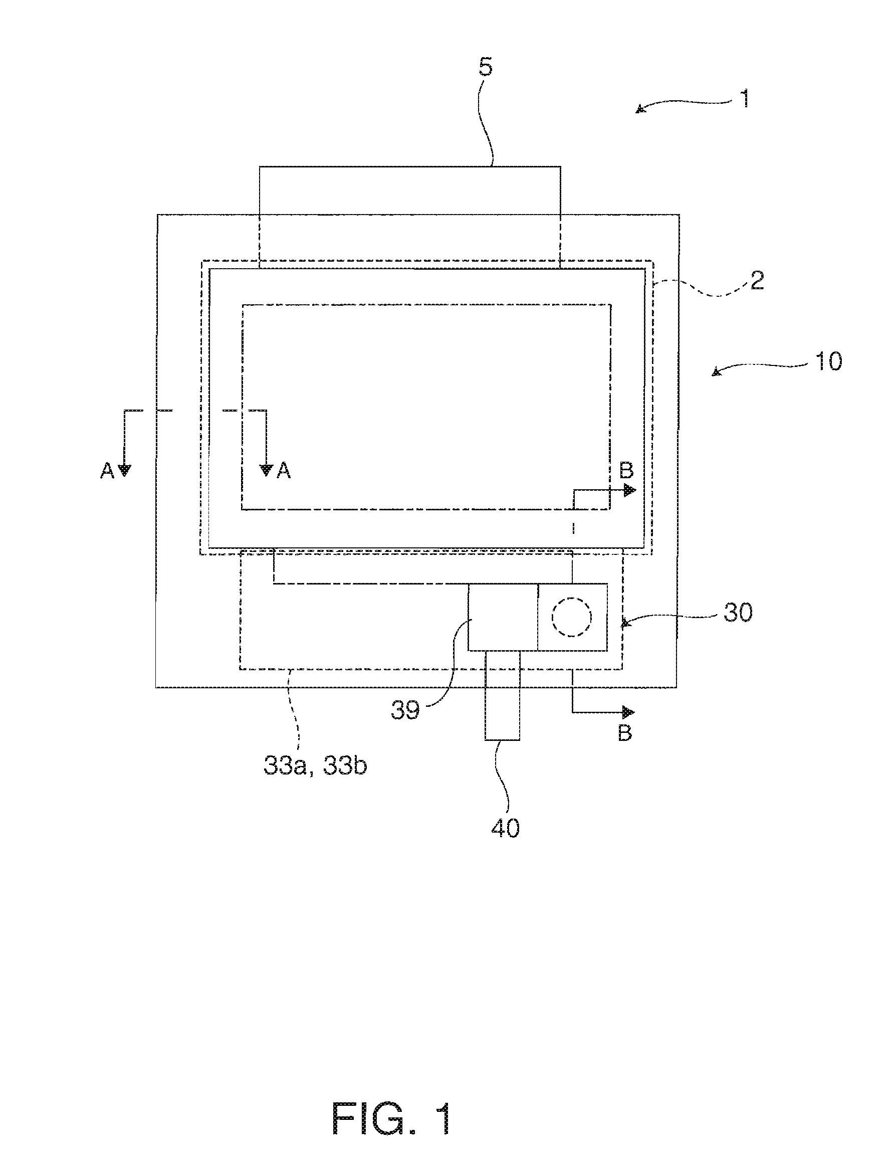
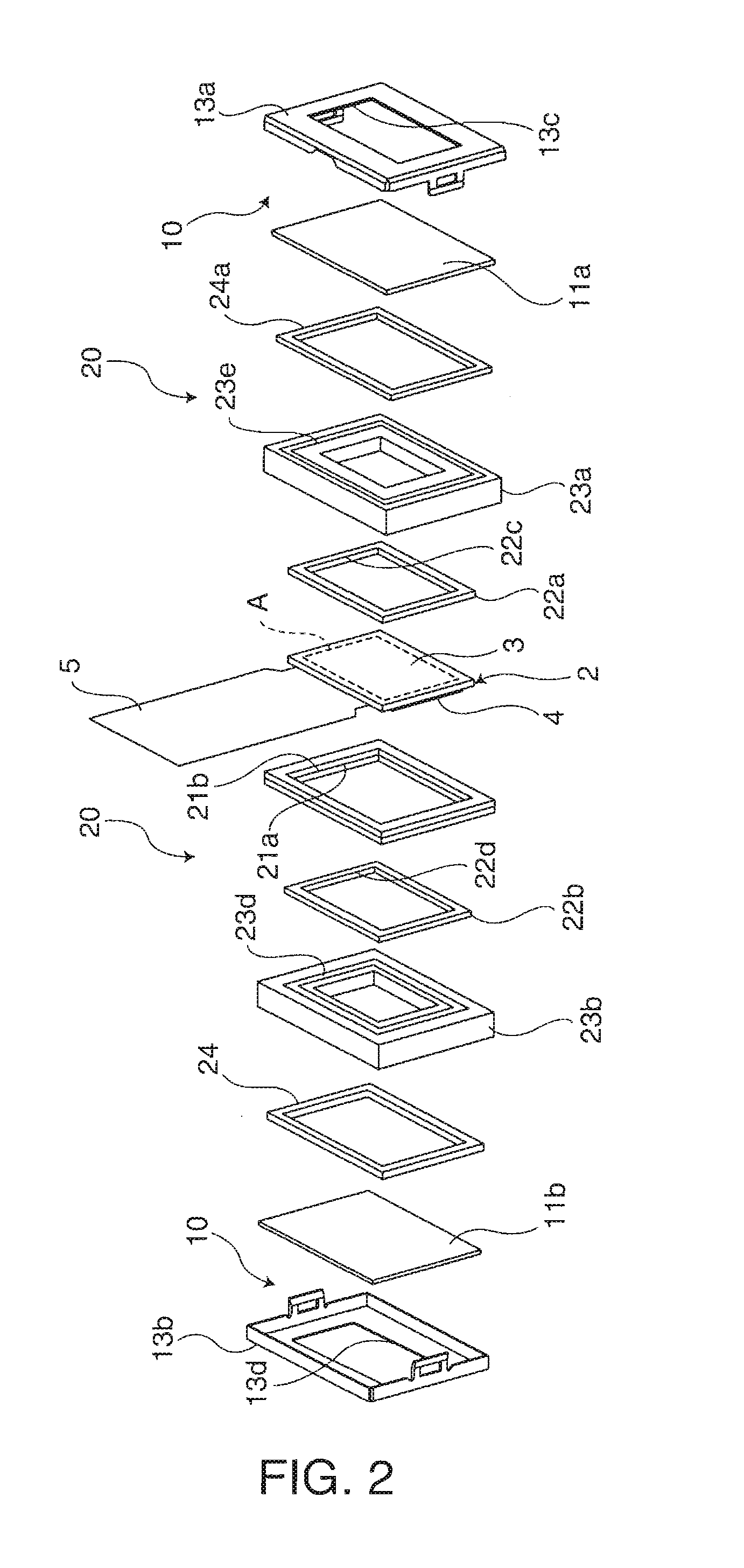
[0055]FIG. 1 is a plan view showing a schematic configuration of the optical device according to this embodiment. FIG. 2 is an exploded perspective view showing essential parts of the optical device of FIG. 1. FIG. 3 is a sectional view taken along line A-A of the optical device of FIG. 1. FIG. 4 is a perspective view of the optical device of FIG. 1. FIG. 5 is a view taken along line B-B of the optical device of FIG. 1.

[0056]A liquid crystal light valve unit (optical device) 1 has a liquid crystal light valve (light modulation element) 2 that modulates a luminous flux emitted from a light source, a holding unit (holding member) 20 that holds the liquid crystal light valve 2, and a convection driving unit 30 that circulates a refrigerant (cooling medium) 31, with the liquid crystal light valve 2, the holding unit 20 and the convection driving unit 30 being provide...

second embodiment

[0089]Next, a second embodiment of the invention will be described with reference to FIGS. 6 to 9. In each of the embodiments described below, the same parts as in the configuration of the liquid crystal light valve unit 1 according to the first embodiment are denoted by the same numerals and will not be described further in detail.

[0090]A liquid crystal light valve unit according to this embodiment differs from the first embodiment in that a piezoelectric ultrasonic motor is used as a driver (driving unit) 50.

[0091]The piezoelectric ultrasonic motor (PZT motor) 50 has a rotatable rotor (rotation start plate of the first embodiment) 51 and a stator (vibrator) 52 having a protrusion 56 contacting the lateral side of the rotor 51, as shown in FIG. 6.

[0092]The rotor 51 is made of stainless steel and its lateral side is a driving surface.

[0093]The stator 52 has a configuration in which thin plate-like piezoelectric elements (piezoelectric ceramics) 53 are provided on both sides of a sta...

third embodiment

[0099]Next, as a third embodiment of the invention, a projector having the liquid crystal light valve unit 1 of the first embodiment will be described.

[0100]FIG. 10 is an explanatory view of a projector 500 having the liquid crystal light valve unit 1 of the embodiment.

[0101]The projector 500 has light sources 512, 513, 514, a liquid crystal light valve unit for red light 522, a liquid crystal light valve unit for green light 523, a liquid crystal light valve unit for blue light 524, a dichroic prism (light combining unit) 525 that combines the color lights emitted from the respective liquid crystal light valve units 522, 523, 524, and a projection lens 526 that projects an optical image combined by the dichroic prism 525. The liquid crystal light valve units 522, 523, 524 are fixed to a dichroic prism fixing member 545 by positioning holes 540 along the lateral sides of the dichroic prism 525, as shown in FIG. 11. In this embodiment, since it is assumed that a refrigerant of high t...


PUM


Abstract

An optical device includes: a light modulation element that modulates a luminous flux emitted from a light source; a casing that houses the light modulation element; a holding member that holds the light modulation element and exposes a part thereof to outside; a refrigerant housed in a housing space surrounded by the casing, the holding member and the light modulation element; and a convection start unit that is provided in the casing and causes convection of refrigerant.

Description

BACKGROUND[0001]1. Technical Field[0002]This invention relates to an optical device and a projector.[0003]2. Related Art[0004]Recently, there has been an image display device using a light modulation element in which light emitted from a light source is cast to a light modulation element such as a liquid crystal panel, the incident light is modulated by the light modulation element, and then the modulated light is projected onto a screen. In such an image display device, the light except for the light projected onto the screen is absorbed by the light modulation element and its peripheral optical elements, generating heat. Thus, a device having a cooler using a gas for radiating the generated heat has been proposed. However, as the density of semiconductors becomes higher, the calorific value per unit volume increases and the cooling with a gas cannot realize sufficient radiation. Therefore, cooling devices using a liquid have been proposed, as disclosed in JP-A-2003-195253, JP-A-20...

Claims


Application Information

Patent Timeline
Patent Type & Authority Applications(United States)
IPC IPC(8): G03B21/16G03B21/18G02B7/00
CPCG03B21/18G03B21/16
Inventor KINOSHITA, SATOSHIZAKOJI, MAKOTO
Owner COLUMBIA PEAK VENTURES LLC
Why Eureka
Try Eureka