Microwave power monitoring

a technology of power monitoring and microwaves, applied in the field of microwave power monitoring, can solve the problems of minor degree of vswr, unnecessary risk and distress to patients, and inability to accurately measure, so as to reduce the width of the frequency range, improve the accuracy of measurement, and speed up the effect of the procedur

Active Publication Date: 2012-10-04
EMBLATION
View PDF13 Cites 22 Cited by
  • Summary
  • Abstract
  • Description
  • Claims
  • Application Information

AI Technical Summary

Benefits of technology

[0017]By varying the frequency of the microwave signal over a frequency range, a more accurate measure of reflection and / or transmission may be obtained. For example, standing wave effects may be more accurately determined.
[0082]The measured ratio signal can be used to determine the port impedance of a connected device and with this knowledge used to generate a signal that can be used as a control means such as a linearization circuit or microprocessor based lookup table to correct a measured signal that would otherwise be influenced by the port impedance thus providing a more accurate measurement.

Problems solved by technology

Conversely an entirely adequate medical device could accidentally be misinterpreted as being faulty causing the user to abandon a treatment causing unnecessary risk and distress to a patient and requiring the treatment to be rescheduled.
Typically components will differ slightly from the reference standards presenting a mismatch that will cause some minor degree of VSWR.
The issue only becomes significant in cases where the component match is poor.
In the case of medical applications the applicator to system match is often worse than the typical industrial component return loss of −20 dB (VSWR 1.22:1) which can result in significant levels of VSWR.
In a system that relies upon measuring the reverse power to denote performance this represents an ambiguous and unreliable measurement.
Such CW generators are often limited to generating microwave energy at a single fixed frequency point, for example 2.45 GHz, due to the use of magnetron based technology that can only provide energy at fixed frequencies.
Variation of device physical parameters in conjunction with CW operation and lack of calibration can result in considerable variation in measurements.
Another factor that is overlooked in known systems is the effect of cascaded mismatches.
That is an often overlooked source of error in microwave measurements.
A limitation in using couplers or impedance dependant measuring components in power detector circuits is that these devices are often suited to measuring against matched terminations.
When connected to a new impedance the setup will continue to refer all measurements to the 50Ω reference standard resulting in uncertainty and unreliability of reflected power measurements where the impedance differs from 50Ω.
The effect of impedance sensitive measurement variation on its own adds a further independent source of error into power measurements.
However that approach is flawed in that the overall system performance is not being improved as the antenna impedance remains unchanged and the power delivered remains the same.
Thus, such systems provide for unreliable measurement of reflected power or VSWR, which cannot be relied upon for safety critical purposes.

Method used


Image

  • Microwave power monitoring
  • Microwave power monitoring
  • Microwave power monitoring

Examples


Embodiment Construction

[0086]Embodiments of the invention are now described, by way of non-limiting example, and are illustrated in the following figures, in which:

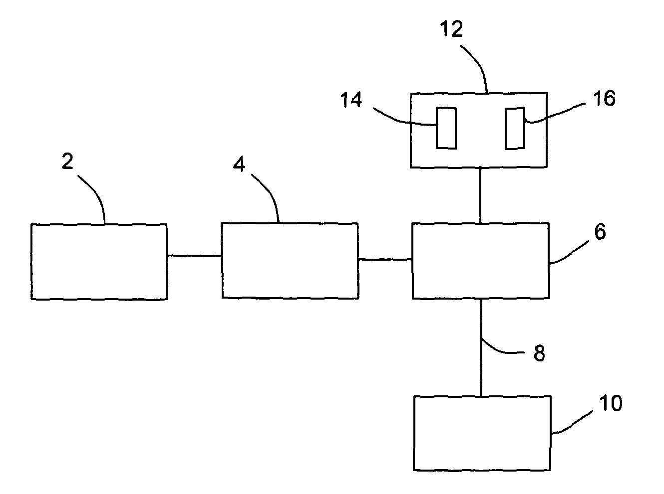
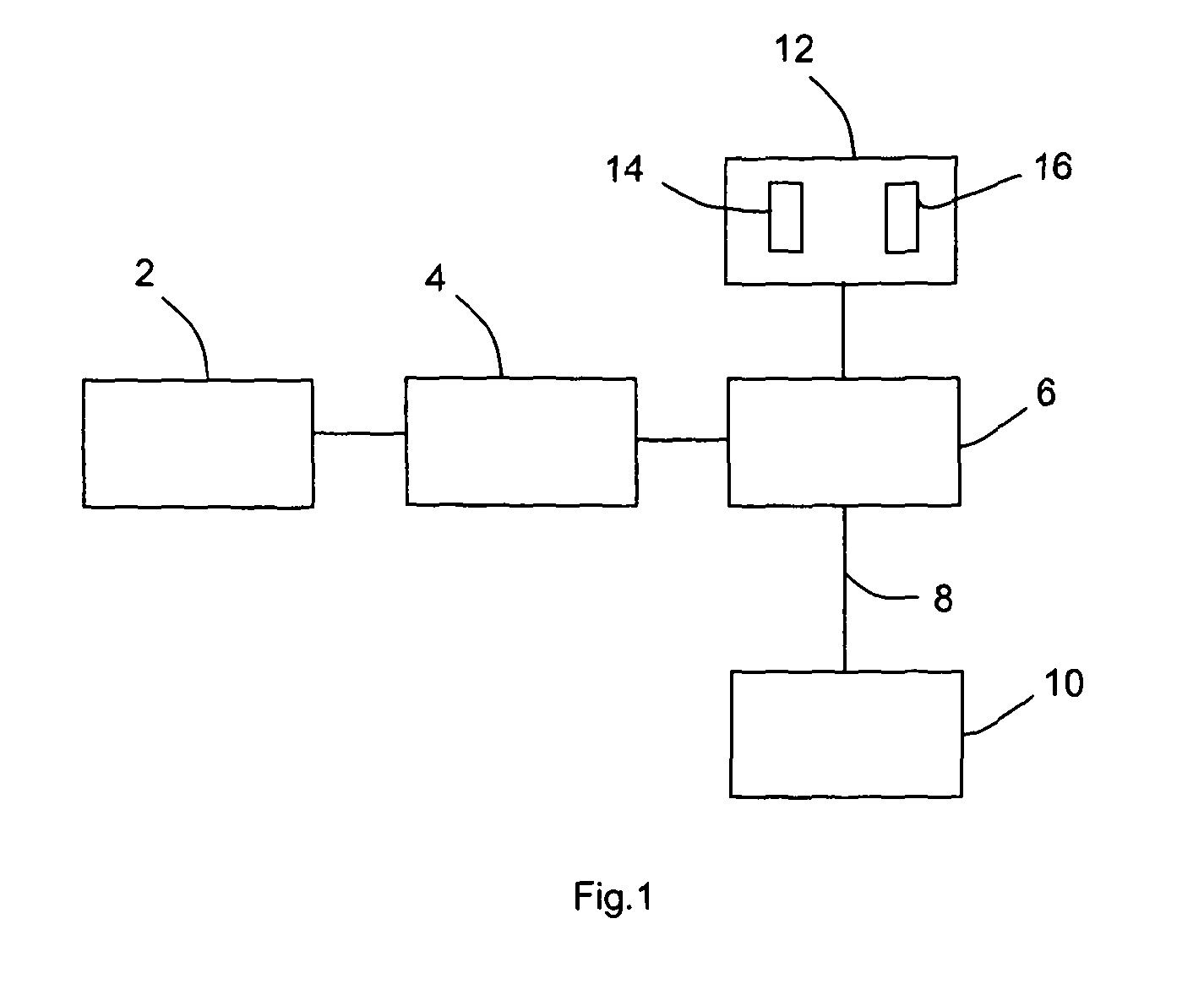
[0087]FIG. 1 is a schematic illustration of an embodiment of a microwave system;

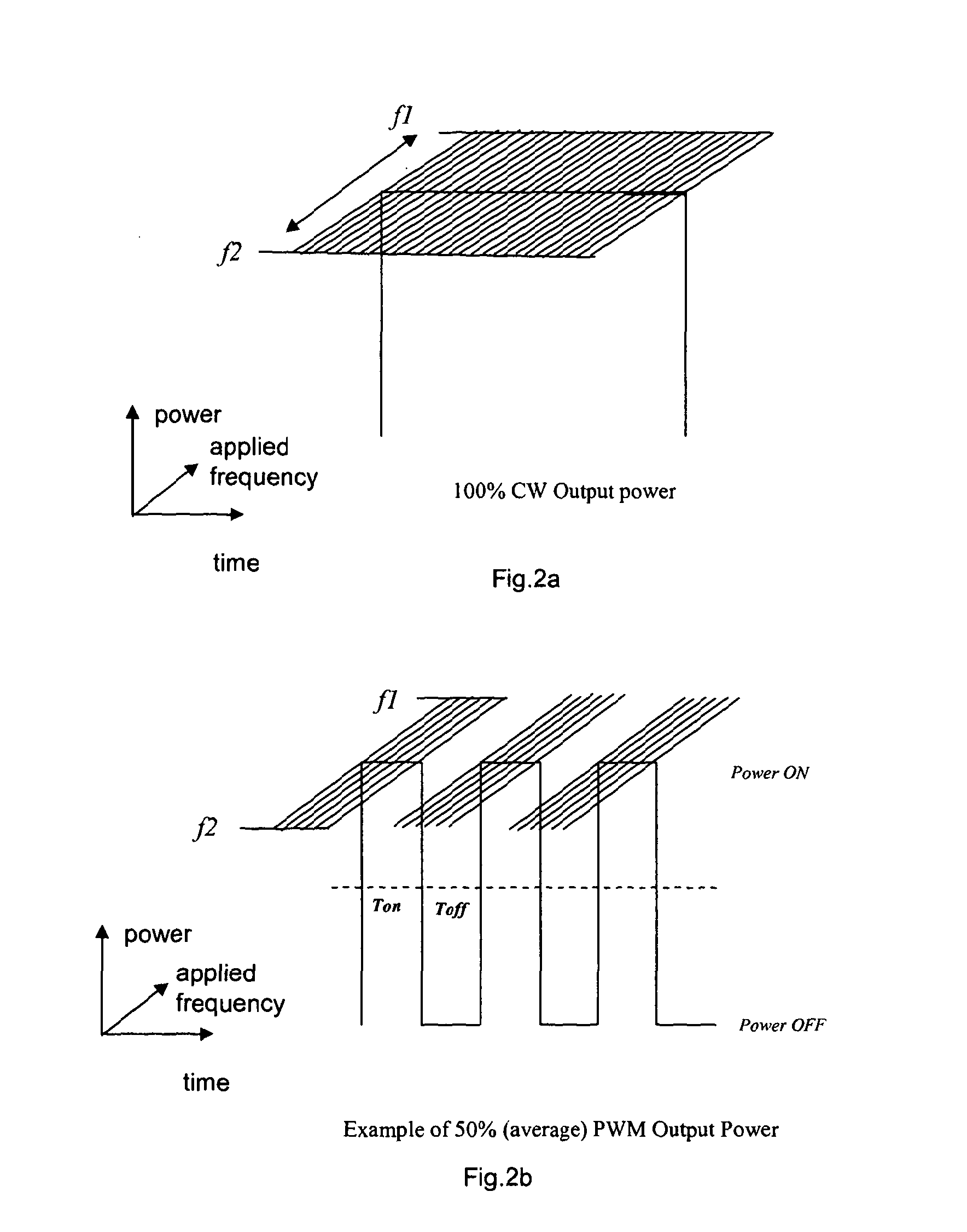
[0088]FIGS. 2a and 2b are schematic illustrations of a variation of output power and applied frequency with time, for continuous wave and pulsed outputs;

[0089]FIG. 3 is a schematic illustration of a microwave system according to an alternative embodiment;

[0090]FIG. 4 is a schematic illustration of the variation of output power and applied frequency with time, for a frequency hopping modulation scheme;

[0091]FIGS. 5 to 12 are graphs of return loss as a function of applied frequency for various combinations of input impedance, transmission line impedance and termination impedance;

[0092]FIG. 13 is a graph of the minimum frequency sweep bandwidth required to capture a full VSWR cycle, as a function of cable length;

[0093]FIG. 14 is a schematic illustration of an embodimen...


PUM


Abstract

A microwave apparatus comprises a microwave source for providing a microwave signal, connectable to a load; control means configured in operation to vary over a frequency range a frequency of the microwave signal provided by the source; a microwave detector for performing microwave measurements, arranged to receive reflections from and / or transmissions to the load in operation and to perform a plurality of measurements, each measurement corresponding to a respective one of a plurality of different frequencies of the frequency range; and means for determining from the plurality of measurements a measure of reflection and / or a measure of transmission.

Description

FIELD OF THE INVENTION[0001]The present invention relates to microwave apparatus and methods, for example apparatus and methods for measuring forward and reflected power at microwave frequencies, including microwave power generator systems and methods that measure forward or reflected power. The apparatus and methods are applicable to both industrial and medical microwave applications.BACKGROUND TO THE INVENTION[0002]The reflected power measurement of known microwave generator systems is typically used as an indirect mechanism for determining the level of applied power (given that the energy deposited in the target material cannot be easily obtained directly). In the event that a predetermined level of reflected power is exceeded the generator system can quickly and safely be shutdown, preventing damage to the equipment and preventing faulty devices operating due to a system misreading.[0003]In medical applications the measurement of reflected power can act as a safety mechanism to ...

Claims


Application Information

Patent Timeline
Patent Type & Authority Applications(United States)
IPC IPC(8): G01R27/04
CPCA61B2018/00785A61B18/1815
Inventor MCERLEAN, EAMONBEALE, GARY
Owner EMBLATION
Why Eureka
Try Eureka