Pan-tilt camera

a pan-tilt and camera technology, applied in the field of pan-tilt cameras, can solve the problems of increasing the temperature of the surroundings of the image processing unit, introducing a lot of heat, etc., and achieve the effect of improving the pt camera

Active Publication Date: 2012-10-04
AXIS
View PDF6 Cites 7 Cited by
  • Summary
  • Abstract
  • Description
  • Claims
  • Application Information

AI Technical Summary

Benefits of technology

[0005]It is an object of the present invention to provide an enhanced PT camera.

Problems solved by technology

This type of computing intense processing requires a lot of current and thereby introduces a lot of heat and thereby increases the temperature of the surroundings of the image processing unit.

Method used


Image

  • Pan-tilt camera
  • Pan-tilt camera
  • Pan-tilt camera

Examples


Embodiment Construction

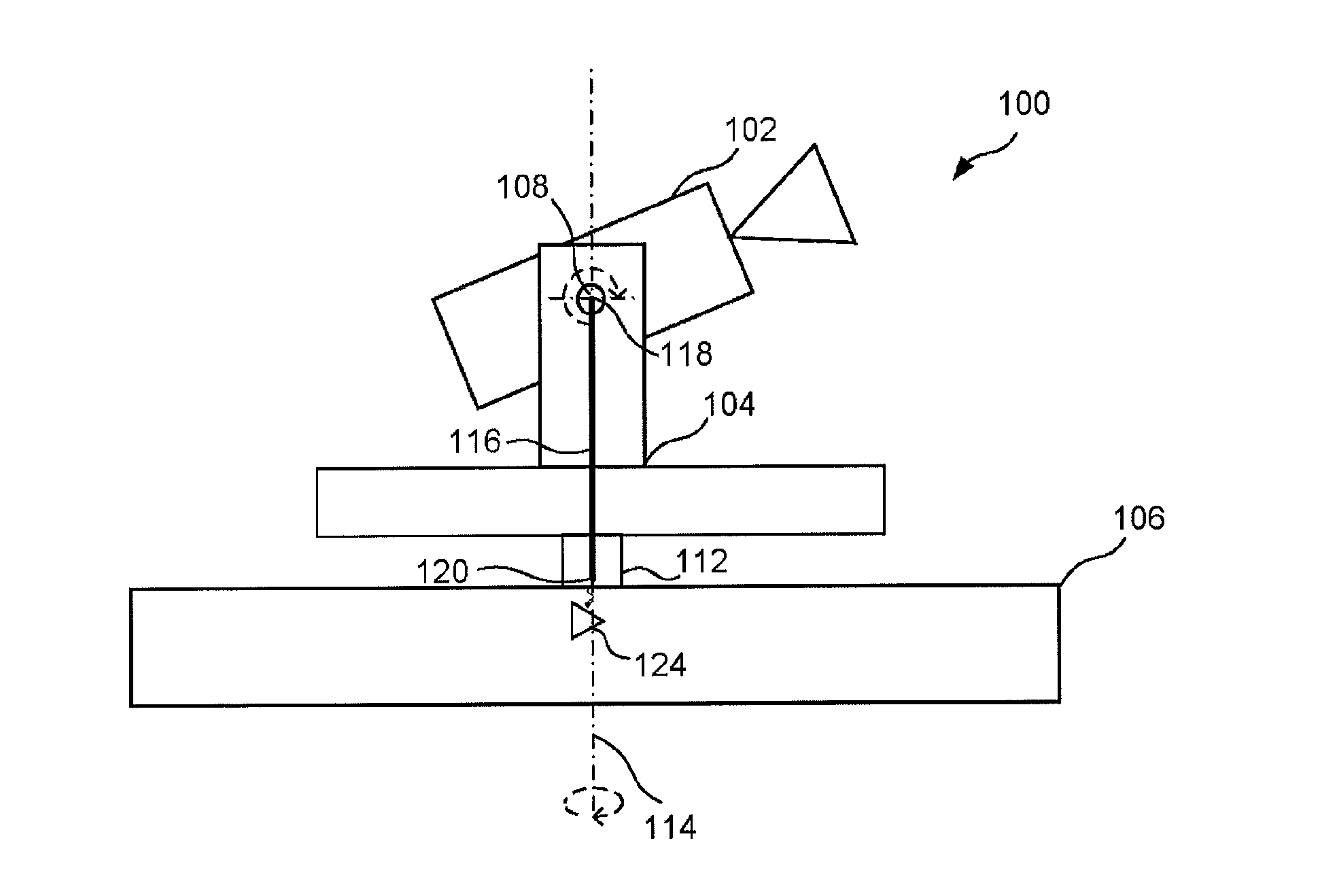
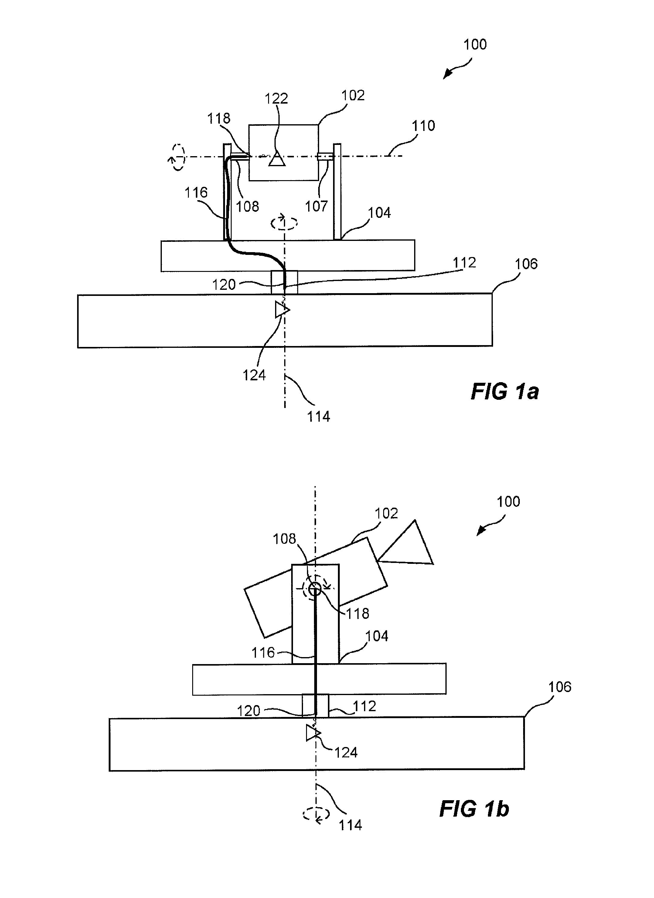
[0045]FIGS. 1a-b show schematic views of a camera unit 100 according to one embodiment of the invention. The camera unit 100 comprises a camera head 102, an intermediate member 104, and a stationary unit 106. The camera head 102 is attached to the intermediate member 104 by means of two joints 107, 108 enabling turning of the camera head 102 around a first axis 110, hereinafter referred to as a tilting axis 110. According to another embodiment the camera head 102 is attached to one joint 107 or 108 and is also turnable around the tilting axis 110. The intermediate member 104 is connected to the stationary unit 106 via yet another joint 112. The joint 112 between the intermediate member 104 and the stationary unit 106 is arranged to enable rotation around a second axis 114 of the intermediate member 104 in relation to the stationary unit 106 by multiple turns, thus enabling turning multiple 360 degree turns of the intermediate member 104 in relation to the stationary unit around the ...


PUM


Abstract

A pan-tilt camera is arranged to include a camera head, a stationary unit, an intermediate member arranged between the camera head and the stationary unit, a first rotary joint rotatably connecting the camera head to the intermediate member, and a second rotary joint, rotatably connecting the intermediate member to the stationary unit. A communication path is provided between the camera head and the stationary unit, including an optical waveguide arranged between the camera head and the stationary unit. The optical waveguide has a first end positioned at the first rotary joint to receive light from the camera head through the first rotary joint. The other end of the waveguide is positioned at the second rotary joint and is arranged to send light to the stationary unit through the second rotary joint.

Description

FIELD OF THE INVENTION[0001]The present invention relates to a pan-tilt camera and to the quality of the captured image.BACKGROUND OF THE INVENTION[0002]Digital pan-tilt cameras, hereinafter referred to as PT cameras, are often used in monitoring and surveillance applications and are therefore often required to capture images with high quality. The quality of the captured images from cameras becomes even more important when the cameras becomes more intelligent and therefore relies even more on that the quality of the images captured for processing in the camera is high.[0003]There are quite many factors that have effect on the quality of an image captured by a digital camera. For example is the lighting of the scene to capture one such factor, less light results in less quality. Other factors are the quality of the lenses and the resolution of the image sensor. Yet another factor is noise from the image sensor of the digital camera. Even when using a High Definition (HD) image senso...

Claims


Application Information

Patent Timeline
Patent Type & Authority Applications(United States)
IPC IPC(8): H04N5/225
CPCG02B6/3604H04N5/23203H04N5/2251H04N23/66H04N23/50H04N23/695H04N23/843
Inventor ALM, CARL-AXELLUNDBERG, STEFANSAGEFALK, WILLY
Owner AXIS
Why Eureka
Try Eureka