
Image recording system, image recording apparatus, and computer usable medium therefor

a technology of image recording and recording equipment, which is applied in the direction of digital output to print units, visual presentations, instruments, etc., can solve the problems of cumbersome or difficult handling of mobile terminals to switch operation screens

Active Publication Date: 2012-10-04
BROTHER KOGYO KK
View PDF7 Cites 41 Cited by
  • Summary
  • Abstract
  • Description
  • Claims
  • Application Information

AI Technical Summary

Benefits of technology

[0007]In view of the difficulty, the present invention is advantageous in that an image recording apparatus, which can effectively display a desirable operation screen to the user in the display unit of the mobile terminal, is provided. Further, an image recording system having the image recording apparatus and the mobile terminal, and a computer usable medium therefore, are provided.
[0010]According to another aspect of the present invention, a non-transitory computer usable medium is provided. the computer usable medium contains computer readable instructions executable by a processor of an image recording apparatus, which is configured to record an image on a recording medium and to wirelessly communicate with a mobile terminal to receive a signal transmitted from the mobile terminal and includes a storage configured to store information concerning a plurality of operation screens. Each of the plurality of operation screens is associated with one of a plurality of continuously incremental ranges partitioned by a predetermined reference distance originating from the image recording apparatus. The computer readable instructions cause the processor to execute functions, including determining a distance between the image recording apparatus and the mobile terminal based on the signal received by the receiver; determining a range, which includes the distance between the image recording apparatus and the mobile terminal, amongst the plurality of ranges; transmitting the information concerning one of the plurality of operation screens associated with one of the plurality of ranges, which includes the distance between the image recording apparatus and the mobile terminal.

Problems solved by technology

If the user wishes to enter other instructions which are not included in the displayed operation screen, the user is required to switch operation screens on the display unit in order to reach a desired operation screen including the desired option; however, handling the mobile terminal to switch the operation screens may be difficult or cumbersome.

Method used


Image

  • Image recording system, image recording apparatus, and computer usable medium therefor
  • Image recording system, image recording apparatus, and computer usable medium therefor
  • Image recording system, image recording apparatus, and computer usable medium therefor

Examples


first embodiment

[0020]Hereinafter, embodiments of the present invention will be described with reference to the accompanying drawings. Firstly, a printing system 70 will be described with reference to FIGS. 1-6.

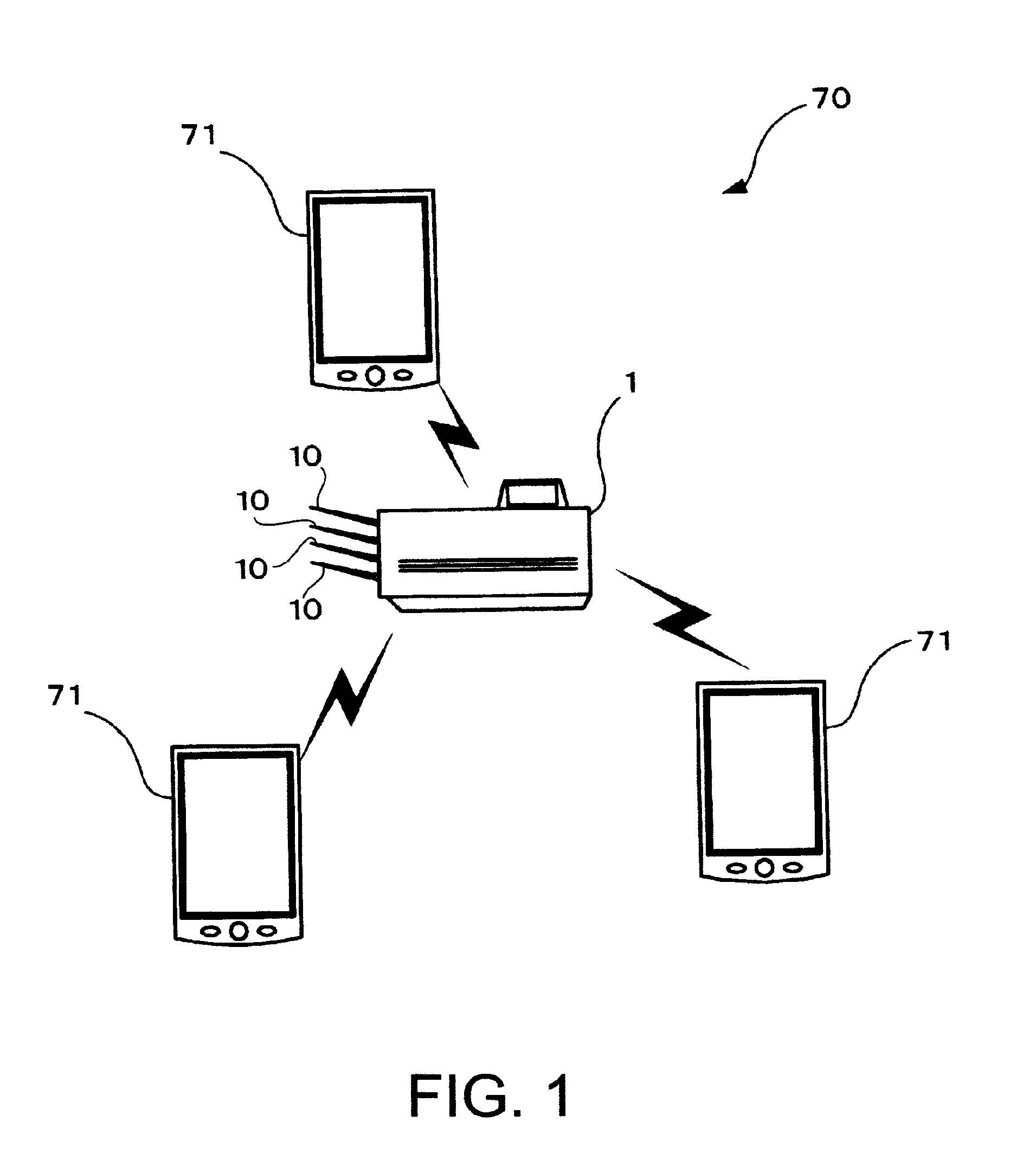
[0021]As shown in FIG. 1, the printing system 70 includes a printer 1 and a plurality of mobile terminals 71. The printer 1 and the mobile terminals 71 can wirelessly communicate with each other via a wireless LAN (local area network). Users of the mobile terminals 71 can enter instructions and information concerning the printer 1 through the mobile terminal 71.

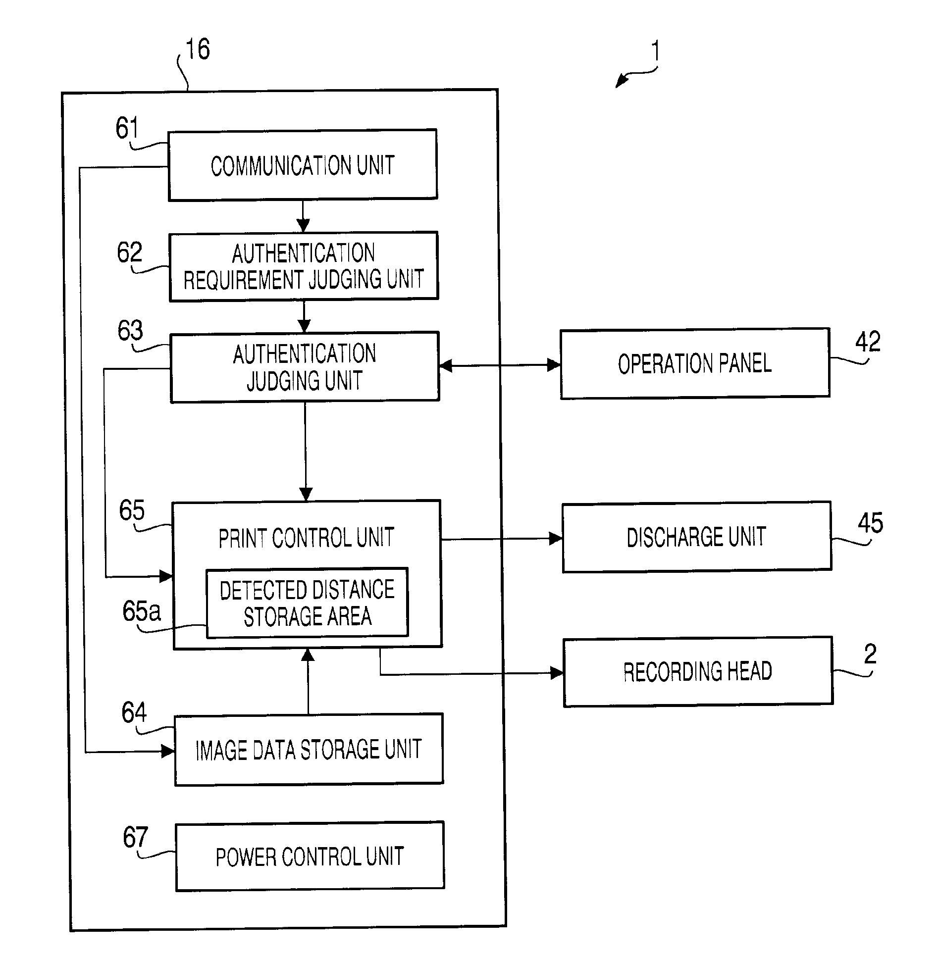
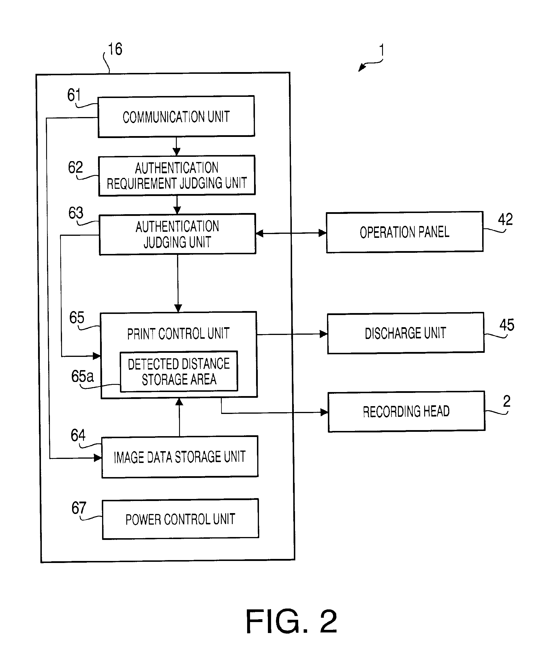
[0022]As shown in FIG. 2, the printer 1 includes a recording head 2, a discharge unit 45, an operation panel 42, and a control unit 16. The recording head 2 can record an image on a recording sheet (not shown). The discharge unit 45 includes a plurality of (e.g., four) discharge trays 10, in which the recording sheet with the image recorded thereon is discharged. The discharge unit 45 further includes a sheet sensor (not shown), whic...

second embodiment

[0058]According to the printing system 70 in the second embodiment, the operation screens can be displayed depending on the distance between the mobile terminal 71 and the printer 1. Therefore, the operation screen, which is more likely to be desired by the user, may be directly presented to the user without requiring the user to experience additional or intervening switching operations to switch screens.

[0059]Although examples of carrying out the invention have been described, those skilled in the art will appreciate that there are numerous variations and permutations of the image recording apparatus that fall within the spirit and scope of the invention as set forth in the appended claims. It is to be understood that the subject matter defined in the appended claims is not necessarily limited to the specific features or act described above. Rather, the specific features and acts described above are disclosed as example forms of implementing the claims.

[0060]For example, in the abo...


PUM


Abstract

An image recording system is provided. The image recording system includes an image recording apparatus, a mobile terminal to wirelessly manipulate the image recording apparatus and including a display device, a receiver to receive a signal from one of the image recording apparatus and the mobile terminal, a distance determining unit to determine a distance between the image recording apparatus and the mobile terminal, a range determining unit to determine a range, which includes the detected distance amongst a plurality of continuously incremental ranges partitioned by a predetermined reference distance originating from the image recording apparatus, a storage to store information concerning a plurality of operation screens associated with the plurality of ranges respectively, and a display controller to control the display device to display one of the plurality of operation screens associated with one of the plurality of ranges, which includes the detected distance.

Description

CROSS REFERENCE TO RELATED APPLICATION[0001]This application claims priority from Japanese Patent Application No. 2011-077842, filed on Mar. 31, 2011, the entire subject matter of which is incorporated herein by reference.BACKGROUND[0002]1. Technical Field[0003]An aspect of the present invention relates to an image recording apparatus, which can be manipulated by a mobile terminal, an image recording system having the image recording apparatus and the mobile terminal, and a computer usable medium therefor.[0004]2. Related Art[0005]A printing system having a printer, which can be manipulated by a mobile terminal, is known. Further, a printer, which can display a specific operation screen to be used by a user of the mobile terminal for manipulating the printer on a display unit of the mobile terminal, is known. The printer may display the operation screen on the display unit when the mobile terminal approaches the printer, and the user may input an instruction to the printer through t...

Claims


Application Information

Patent Timeline
IPC IPC(8): G06F3/12G06K15/02
CPCG06F3/1204H04N2201/3205G06F3/1238G06F3/1259G06F3/1292H04N1/00307H04N1/00477H04N1/00697H04N1/00771H04N1/00896H04N1/32106H04N1/4413H04N2201/0036H04N2201/0039H04N2201/0055H04N2201/3278H04N2201/0082G06F3/1207
Inventor ITOGAWA, YOSHIHIROKISHIMOTO, NORIAKI
Owner BROTHER KOGYO KK
Learn More