Electric power conversion apparatus

Active Publication Date: 2012-10-04
DENSO CORP
View PDF9 Cites 28 Cited by
  • Summary
  • Abstract
  • Description
  • Claims
  • Application Information

AI Technical Summary

Benefits of technology

[0038]As described previously, it is possible to effectively suppress increase in the ambient temperature in the entire space inside the housing; thus, it is possible to ensure the heat resistance of the electric power conversion apparatus. Moreover, with the arrangement of the first and second electric power convers

Problems solved by technology

Moreover, electric power conversion devices generally generate a large amount of heat due to the large electric currents flowing therein.
However, even with the two cooling devices, local increase in the am

Method used


Image

  • Electric power conversion apparatus
  • Electric power conversion apparatus
  • Electric power conversion apparatus

Examples


first embodiment

[First Embodiment]

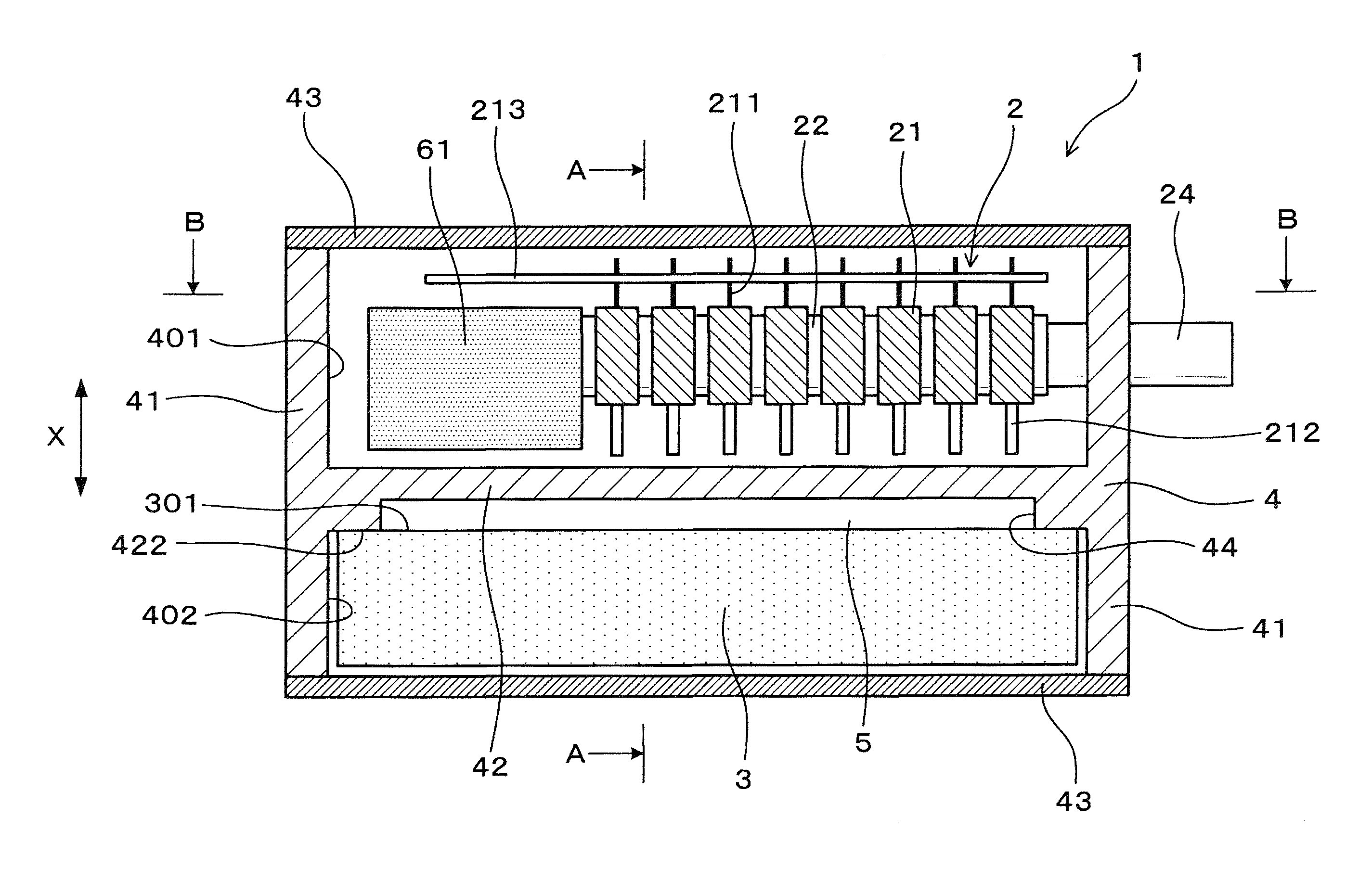
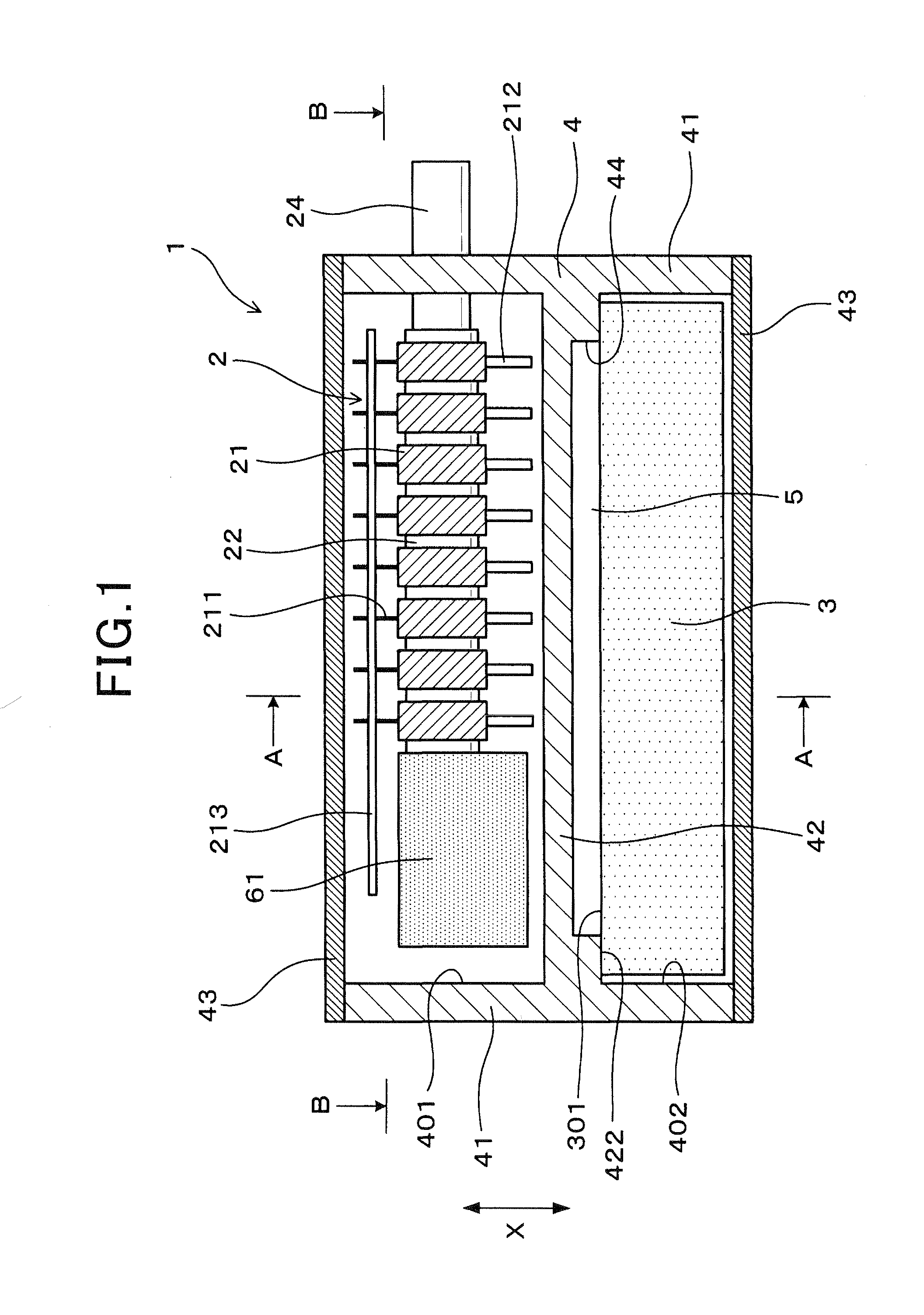
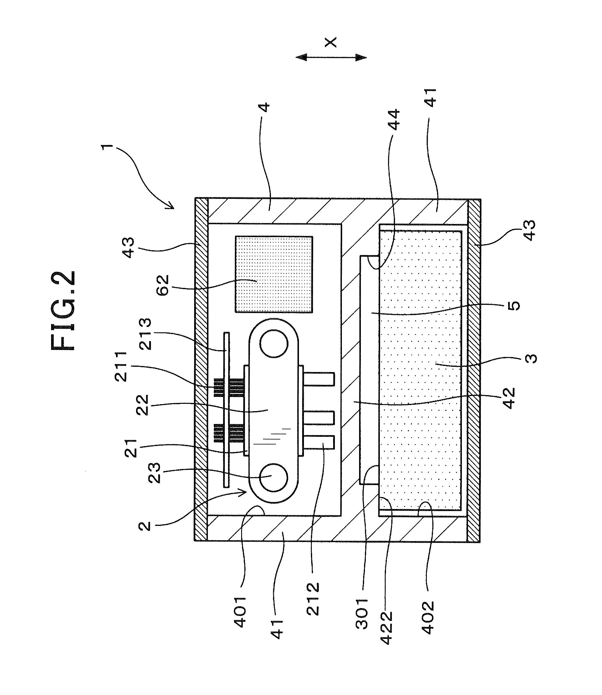
[0049]Referring to FIGS. 1-3, an electric power conversion apparatus 1 according to a first embodiment includes first and second electric power conversion devices 2 and 3 that are arranged to overlap each other in the vertical direction X, and a housing 4 that receives both the first and second electric power conversion devices 2 and 3 therein. The housing 4 has a partition wall 42 that is formed to partition the housing 4 between the first and second electric power conversion devices 2 and 3. In other words, the partition wall 42 extends between the first and second electric power conversion devices 2 and 3 to partition the housing 4 into two parts in which the first and second electric power conversion devices 2 and 3 are respectively received. Further, the partition wall 42 has a coolant passage 5 formed therein.

[0050]Specifically, in the present embodiment, as shown in FIGS. 1 and 2, the housing 4 has four side walls 41 each extending vertically and the partiti...

second embodiment

[Second Embodiment]

[0088]This embodiment illustrates an electric power conversion apparatus 1 which has almost the same configuration as the electric power conversion apparatus 1 according to the first embodiment; accordingly, only the differences therebetween will be described hereinafter.

[0089]In the first embodiment, the recess 44 formed in the lower surface 422 of the partition wall 42 of the housing 4, which makes up the coolant passage 5, is covered by the converter 3 that is disposed in contact with the lower surface 422 of the partition wall 42.

[0090]In comparison, in the present embodiment, as shown in FIG. 4, the recess 44 formed in the lower surface 422 of the partition wall 42 of the housing 4 is covered by a plate-shaped lid member 45 that is disposed in contact with the lower surface 422 of the partition wall 42. Consequently, an upper surface 451 of the lid member 45 faces the coolant passage 5 and is thus directly exposed to the coolant flowing through the coolant pa...

third embodiment

[Third Embodiment]

[0095]This embodiment illustrates an electric power conversion apparatus 1 which has almost the same configuration as the electric power conversion apparatus 1 according to the first embodiment; accordingly, only the differences therebetween will be described hereinafter.

[0096]In the first embodiment, the partition wall 42 of the housing 4 has only the single coolant passage 5 formed therein (see FIG. 2).

[0097]In comparison, in the present embodiment, as shown in FIG. 5, the partition wall 42 of the housing 4 has a pair of first and second coolant passages 5 formed therein.

[0098]The first coolant passage 5 is identical to the coolant passage 5 in the first embodiment. That is, the first coolant passage 5 is made up of a recess 44 which is formed in the lower surface 422 of the partition wall 42 and covered by the converter 3 that is disposed in contact with the lower end surface 422.

[0099]On the other hand, the second coolant passage 5 is made up of a recess 46 whi...


PUM


Abstract

An electric power conversion apparatus includes first and second electric power conversion devices and a housing. The first and second electric power conversion devices are arranged to overlap each other in an overlap direction. The housing receives both the first and second electric power conversion devices therein. The housing has a partition wall that extends between the first and second electric power conversion devices to partition the housing into first and second parts in which the first and second electric power conversion devices are respectively received. The partition wall has a coolant passage formed therein, thereby allowing a coolant to flow through the coolant passage.

Description

CROSS-REFERENCE TO RELATED APPLICATIONS[0001]This application is based on and claims priority from Japanese Patent Applications No. 2011-72706 filed on Mar. 29, 2011 and No. 2011-237807 filed on Oct. 28, 2011, the contents of which are hereby incorporated by reference in their entireties into this application.BACKGROUND[0002]1. Technical Field[0003]The present invention relates to electric power conversion apparatuses that include electric power conversion devices such as an inverter and a converter.[0004]2. Description of the Related Art[0005]Motor vehicles, such as an electric vehicle and a hybrid vehicle, are generally equipped with electric power conversion devices such as an inverter that converts DC (Direct Current) power into AC (Alternating Current) power and a converter that converts DC power of one voltage into DC power of another voltage.[0006]Moreover, electric power conversion devices generally generate a large amount of heat due to the large electric currents flowing t...

Claims


Application Information

Patent Timeline
IPC IPC(8): H05K7/20
CPCH05K7/20927H01L2924/0002H01L2924/00
Inventor IGUCHI, SATOSHI
Owner DENSO CORP
Why Eureka
Try Eureka