Systems and Methods for Airborne Particle Contamination Control

Inactive Publication Date: 2012-10-04
THE PROCTER & GAMBLE COMPANY
View PDF3 Cites 23 Cited by
  • Summary
  • Abstract
  • Description
  • Claims
  • Application Information

AI Technical Summary

Benefits of technology

[0003]The present invention relates to a method for airborne particle contamination control, comprising: creating a simulation by modeling a turbulent airflow in an environment that includes an equipment of interest; plotting a flow parameter on the simulation to visualize a flow field of air according to a current design; creating an injection point on the simulation for particles in the environment; determining a particle concentration of the particles; determining, by a computing device and from the particle concentration, whether the current design provides contamination control; in response to determining that the current design does not provide contamination control, creating a modified design; and providing the modified design for implementation.
[0004]The present invention further relates to a computing device for airborne particle contamination control, comprising: a memory component that stores airflow prediction logic and simulation logic, the simulation logic causing the computing device to create a simulation of a turbulent airflow in an environment, that includes an equipment of interest, the airflow prediction logic causing the computing device to perform at least the following: plot a flow parameter on the simulation to visualize a flow field of air in the environment; identify, from the flow parameter, an area of interest; create an injection point on the simulation for particles in the environment; determine a particle con

Problems solved by technology

These airborne particles may cause discomfort concerns to persons in the environments, health concerns to persons in the environments, fire hazards, equipment malfunction, product issues, and/or other issues.
As an example, in many factory settings, various airborne particulates are creat

Method used


Image

  • Systems and Methods for Airborne Particle Contamination Control
  • Systems and Methods for Airborne Particle Contamination Control
  • Systems and Methods for Airborne Particle Contamination Control

Examples


Embodiment Construction

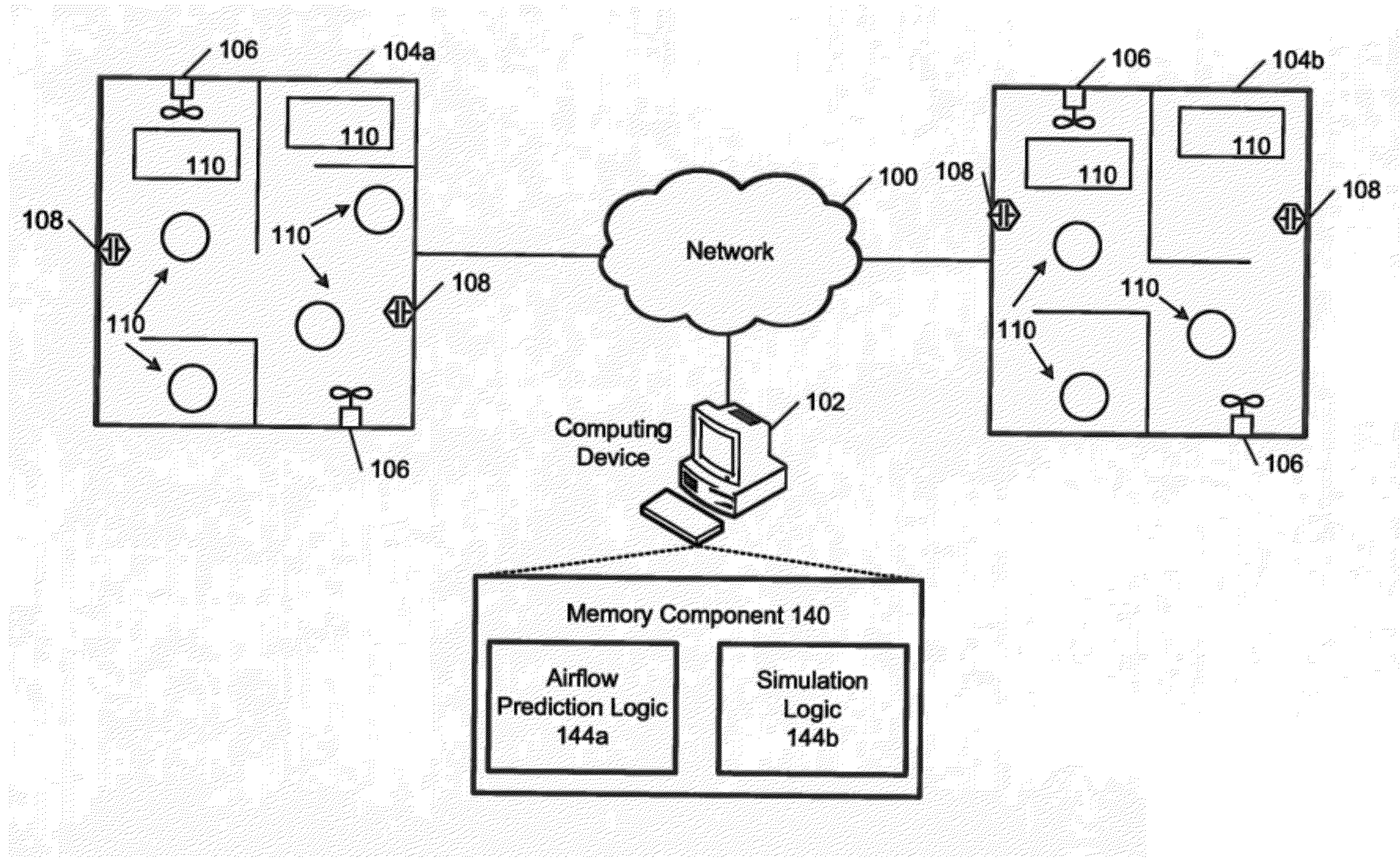
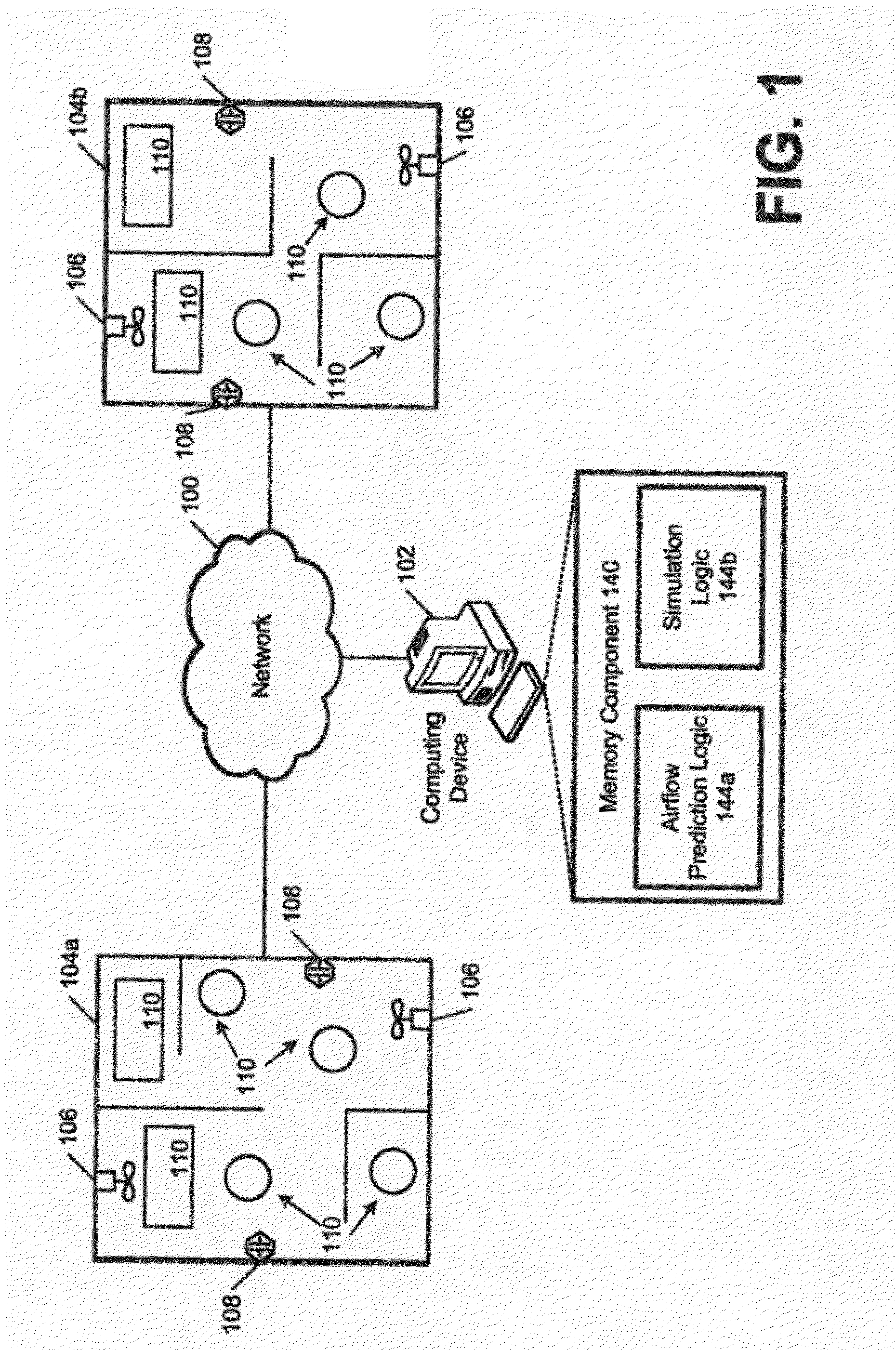
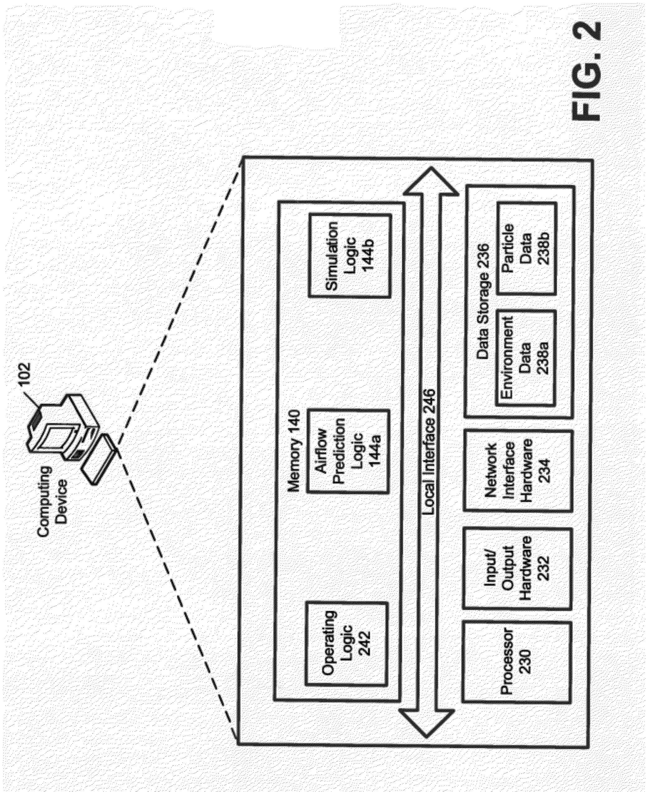
[0017]The present inventions are directed to systems and methods for predicting airflow to control airborne particle contamination. The systems and methods may be configured to simulate an environment that includes at least one piece of equipment. The environment may be a factory, home, office, warehouse, and / or other place where airborne particles pose a threat to the comfort and / or health of people or equipment in that environment. The simulation may include a determination regarding the flow of air in the environment. Creating the simulation may comprise at least one of the following: utilizing a computational fluid dynamics analysis, solving single-phase incompressible Navier-Stokes equations, solving single-phase compressible Navier-Stokes equations, determining steady state solutions, or determining transient solutions. Additionally, based on a predetermined type of particle in the air, such as an airfelt dust, a film dust, a dry laundry powder, a glue in non-contact applicati...


PUM


Abstract

The present invention relates to a method for airborne particle contamination control, comprising: creating a simulation by modeling a turbulent airflow in an environment that includes an equipment of interest; plotting a flow parameter on the simulation to visualize a flow field of air according to a current design; creating an injection point on the simulation for particles in the environment; determining a particle concentration of the particles; determining, by a computing device and from the particle concentration, whether the current design provides contamination control; in response to determining that the current design does not provide contamination control, creating a modified design; and providing the modified design for implementation. The present invention further relates to a computing device for airborne particle contamination control. The present invention still further relates to a non-transitory computer-readable medium for airborne particle contamination control.

Description

FIELD OF THE INVENTION[0001]The present application relates generally to predicting airflow and specifically to predicting the movement of airborne particles to more efficiently capture the airborne particles.BACKGROUND OF THE INVENTION[0002]In many environments, such as homes, factories, warehouses, etc., airborne particles, such as glues, smokes, dust, organic materials, etc. are created. These airborne particles may cause discomfort concerns to persons in the environments, health concerns to persons in the environments, fire hazards, equipment malfunction, product issues, and / or other issues. As an example, in many factory settings, various airborne particulates are created from a manufacturing process that can be harmful to those people in the factory. While many of these environments are equipped with one or more ventilation systems, oftentimes, the ventilations systems provide inadequate airflow to route and / or capture a desired amount of the particles.SUMMARY OF THE INVENTION...

Claims


Application Information

Patent Timeline
IPC IPC(8): G06G7/57
CPCG06F2217/16F24F11/006Y02B30/78F24F2011/0023G06F17/5009F24F11/30F24F2110/64F24F11/62G06F2111/10G06F30/20Y02B30/70F24F11/64F24F11/58
Inventor POONDRU, SHIRDISHALLENDE-BLANCO, MELKITCHING, JOSEPH FRANCISAYDORE, SAVASEROGLU, HASANCOMSTOCK, KRISTA BETHFENG, JIANJUNYANG, YUNPENGMCKIBBEN, JOHN FERNEYCOMER, JR., JAMES KENNETH
Owner THE PROCTER & GAMBLE COMPANY
Why Eureka
Try Eureka