Inflation and monitoring assembly for a pressure cuff

a technology of inflation and monitoring assembly, which is applied in the direction of catheters, medical devices, other medical devices, etc., can solve the problems of not being reusable, and achieve the effect of convenient visual observation, easy and efficient monitoring of pressure within the cuff, and easy determinability

Inactive Publication Date: 2012-10-11
SEEDLINGS LIFE SCI VENTURES
View PDF1 Cites 2 Cited by
  • Summary
  • Abstract
  • Description
  • Claims
  • Application Information

AI Technical Summary

Benefits of technology

[0016]Other operative and structural features include a window disposed on the casing to facilitate the visual observation of at least a portion of the indicator member. As a result, personnel may easily and efficiently monitor the pressure within the cuff by visually determining the position of the indicator member within the casing. Moreover, the portion of the indicator member viewable through the window may include informative alpha / numeric indicia, color coding, etc. which provides the observer with a clear and easily determinable visual indication as to an acceptable or non-acceptable pressure level within the retaining cuff. In addition, in order to further facilitate the visual observation of the pressure reading, the window may incorporate a magnifying lens or similar structure to make viewing easier. Yet additional embodiments of the present invention may include an LED or other appropriate digital readout, as well as an audible and / or visual warning in the event of an over inflation condition of the cuff. Also, the inflation and monitoring assembly may be structured to facilitate locating and / or using it when in a darkened room. Such features may include, but are not limited to, the illumination or “glowing” of the casing and / or other components of the assembly when it is used or stored in a darkened area.
[0017]Additional structural and operative features of the inflation and monitoring assembly of the present invention include a pressure relief valve assembly including at least one relief valve mounted on the casing in an exteriorly accessible location. Further, the pressure relief valve is disposed in direct fluid communication with the interior of the pressure chamber and in regulating relation to fluid flow vented from the pressure chamber to an exterior of the casing. As a result, the selective manipulation of the relief valve will cause a “bleeding” or venting of air or fluid from within the pressure chamber to the exterior of the casing. As a result the pressure within both the pressure chamber and the retaining cuff may be reduced when it is determined that such pressure is excessive. In addition, the structuring of the relief valve may be tapered or otherwise appropriately structured to provide for a gradual bleeding or release of pressure from within the pressure chamber.
[0024]When so positioned, the orienting members will be substantially fixed within or relative to the retaining structure. As a result, when the restrictor is in the inoperative position, it is disposed in obstructing relation to the inflating lumen connector, thereby preventing or restricting the positioning of the restrictor by the connector into the operative position. Moreover, the obstructing position of the restrictor will restrict the inflating lumen connector from entering the adaptor housing to a position where the connector can establish the aforementioned path of fluid flow with the outlet port connector of the casing. Therefore, the adaptor assembly including the provision of the retaining structure and the interaction thereof with the orienting assembly will define a single use connection between the retaining cuff and the inflating lumen. However, it is again emphasized that the adaptor assembly including the provision of the retaining structure and the interaction thereof with the orienting assembly could be effective in defining a single use connection between different but cooperatively structured medical devices especially, but not limited to, where one of the devices includes a luer type connector.
[0026]As set forth above, at least one embodiment of the adaptor assembly is structured to establish a single use connection of the removal fluid source with the casing. Accordingly, additional structural and operative features of the adaptor assembly may include a retaining structure disposed within the housing in engageable relation with the restrictor. The retaining structure is cooperatively structured with the restrictor so as to fixedly maintain the restrictor in the aforementioned inoperative position. Moreover, the inoperative position may be more specifically defined by the retractor being fixed in an obstructing position relative to the discharge portion of the removable fluid source. This obstructing position will prevent connection of the discharge portion of the fluid source and the outlet port of the casing, thereby preventing the establishment of the aforementioned path of fluid flow. The obstructing position of the restrictor being fixed will also prevent the pump assembly from forcing movement of the restrictor into the aforementioned operative position within the housing.

Problems solved by technology

As a result, once the casing of the assembly is disconnected from the inflating lumen, it is not reusable at least to the extent of being reconnected to the inflating lumen.

Method used


Image

  • Inflation and monitoring assembly for a pressure cuff
  • Inflation and monitoring assembly for a pressure cuff
  • Inflation and monitoring assembly for a pressure cuff

Examples


Embodiment Construction

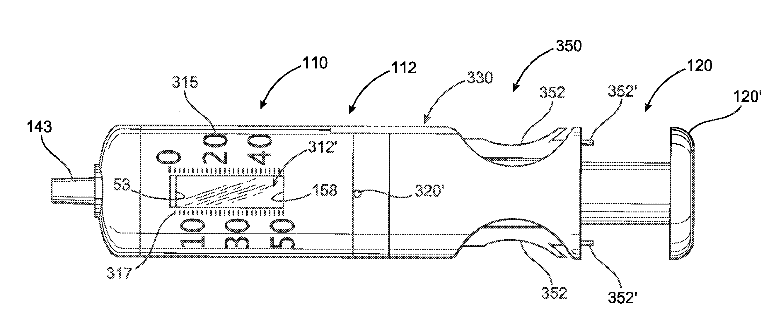
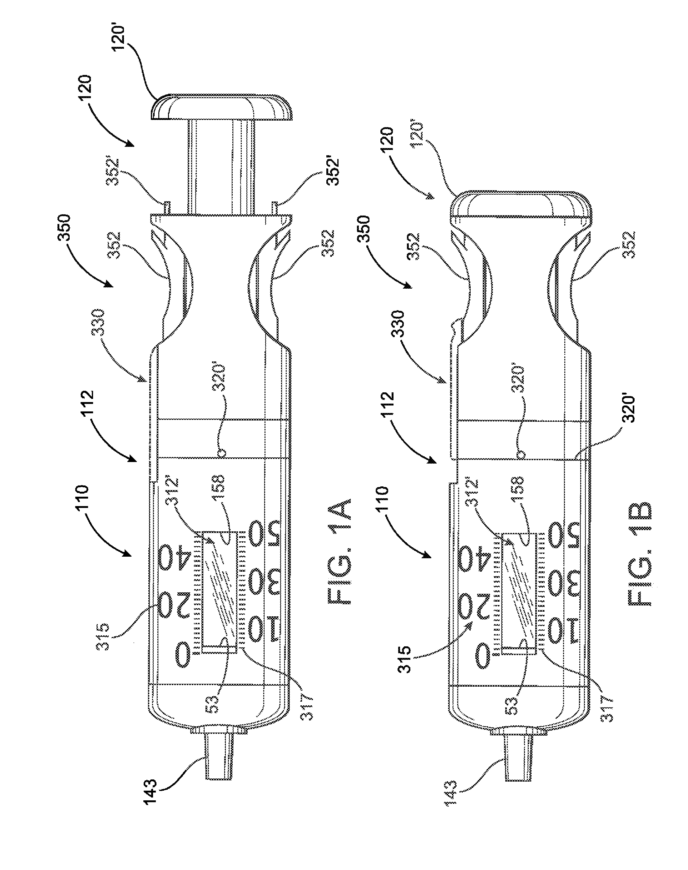
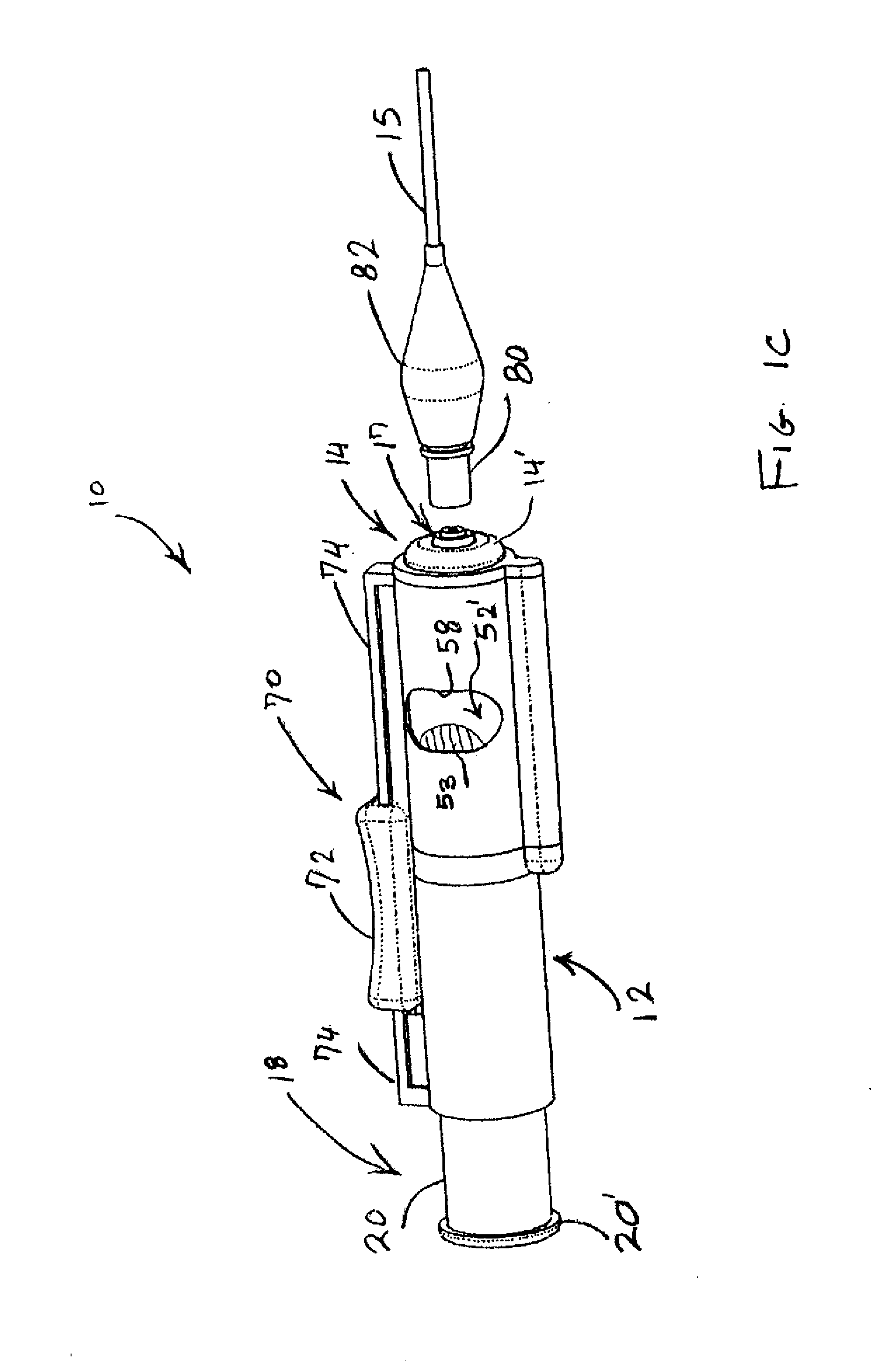
[0061]As shown in the accompanying drawings, the present invention is directed to an inflation and pressure monitoring assembly generally indicated as 10. The assembly 10 structured to inflate and monitor the pressure within a retaining cuff or pressure cuff of a medical device, including in the preferred embodiment the type associated with an endotracheal tube. It is understood, however, that the pressure cuff, often referred to as a balloon in some devices, could be included as part of medical devices used in balloon kyphoplasty, balloon sinuplasty, coronary or vascular balloon angioplasty and / or the delivery of stents, balloon esophageal dilation, and the dilation of strictures and sphincters, balloon dilatation of the nephrostomytract, and / or Swan Ganz catheters, among other medical devices.

[0062]More specifically, the assembly 10 includes a generally elongated casing 12 having a distal end generally indicated as 14 structured to be interconnected to an inflation lumen 15, which...


PUM


Abstract

An assembly structured to inflate a retaining or pressure cuff of a medical device of the type associated with artificial airway tube and concurrently monitor pressure therein. A pump assembly is movably connected to a casing and structured to force fluid flow, for inflation of a pressure chamber of the casing. An indicator member is visually accessible through a casing window and is variably positionable dependent on and indicative of existing pressure within the retaining cuff. The existing pressure within the pressure chamber is substantially equivalent to that within the retaining cuff thereby facilitating the variable position of the indicator member being indicative of pressure within the retaining cuff. A junction between the casing and an inflation lumen is structured to allow disconnection and prevent reconnection between the casing and the lumen.

Description

CLAIM OF PRIORITY [0001]The present application is a continuation-in-part application of previously filed, now pending application having Ser. No. 13 / 005,359, filed on Jan. 12, 2011, which is a continuation-in-part application of previously filed, now pending application having Ser. No. 12 / 806,810, filed on Aug. 20, 2010, which is a continuation-in-part application of previously filed, now pending application having Ser. No. 12 / 661,103, filed on Mar. 10, 2010 all of which are incorporated herein by reference in their entirety.BACKGROUND OF THE INVENTION[0002]1. Field of the Invention[0003]This invention is directed to an assembly structured to inflate and continuously monitor pressure within an inflatable cuff, such as a retaining cuff for an endotracheal tube and / or tracheostomy tube. A casing and a pump assembly are collectively operative to inflate the cuff and monitor existing pressure therein. The casing may be alternately structured for fixed or removable securement to either ...

Claims


Application Information

Patent Timeline
Patent Type & Authority Applications(United States)
IPC IPC(8): A61M16/04
CPCA61M16/044A61M16/0434A61M2205/073A61M2205/273A61M2205/276A61M2205/581A61M2205/583A61M2205/584A61M2205/585A61M2205/587A61M25/10187A61M25/10184A61M25/10185
Inventor LOWENSTEIN, STEPHEN JAYWINTERS, NATHANCOLE, MICHAEL R.LESSNAU, KLAUS D.RUBIN, KEITHSELLERS, JAMES M.
Owner SEEDLINGS LIFE SCI VENTURES
Why Eureka
Try Eureka