Method and Apparatus for Forming and Mounting a Photovoltaic Array

a photovoltaic array and photovoltaic technology, applied in the direction of heat collector mounting/support, light and heating apparatus, pv power plants, etc., can solve the problems of other limitations of the related art, and achieve the effect of rapid twist-lock engagement and improved structural load distribution

Inactive Publication Date: 2012-10-11
SOLARCITY
View PDF0 Cites 54 Cited by
  • Summary
  • Abstract
  • Description
  • Claims
  • Application Information

AI Technical Summary

Benefits of technology

[0008]The inventive apparatus may provide a slidable parallel coupling for securely interlocking the outside surfaces of parallel frame members together in a side to side arrangement, thereby enabling the formation of a PV array with improved structural load distribution. The inventive coupling member may attach to a slot in the frame at substantially any position along the length of the frame thereby enabling the interconnection of adjacent PV modules along both an x and y axis. The inventive apparatus may further provide a rotating portion and locking portion for coupling to frame attachment, mounting brackets for direct connection to a mounting surface, grounding teeth for the automatic creation of a reliable two axis grounding matrix, and a rapid twist-lock engagement means for reliably interlocking and aligning PV modules in the array. [9] In addition to the exemplary aspects and embodiments described above, further aspects and embodiments will become apparent by reference to the figures and by study of the following detailed descriptions.

Problems solved by technology

Other limitations of the related art will become apparent to those of skill in the art upon a reading of the specification and a study of the figures.

Method used


Image

  • Method and Apparatus for Forming and Mounting a Photovoltaic Array
  • Method and Apparatus for Forming and Mounting a Photovoltaic Array
  • Method and Apparatus for Forming and Mounting a Photovoltaic Array

Examples


first embodiment

[0088]The first embodiment of the present invention provides numerous advantages over prior art systems. Inventive features of the present apparatus include, but are not limited to the following:

[0089]Parallel coupling action—parallel coupling is attachable to substantially the whole length of all four sides of a PV module and securely locks the outside surfaces of parallel frame members together in a side to side arrangement, thereby increasing the structural performance of the PV array.

[0090]Three mode design—Parallel coupling is shiftable with a wrench into three modes of operation: positioning mode, sliding mode, and locked mode. A positive stop is provided when locked mode is reached.

[0091]Locking portion—Parallel coupling provides two specially shaped locking portions which are insertable into slots on the outside surfaces of adjacent frame members. Locking portions enable discrete positions of device and provide a positive stop for locked position.

[0092]Dual bearing action—Pa...

second embodiment

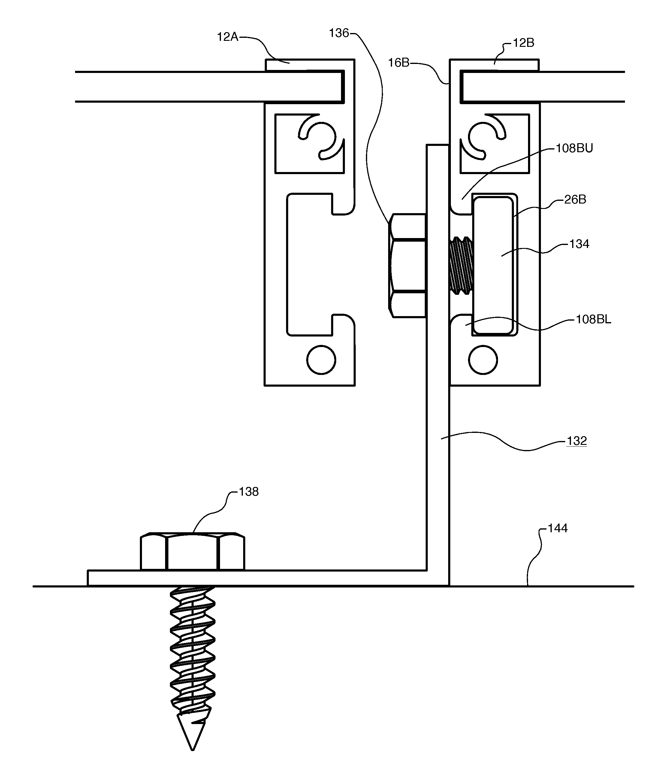
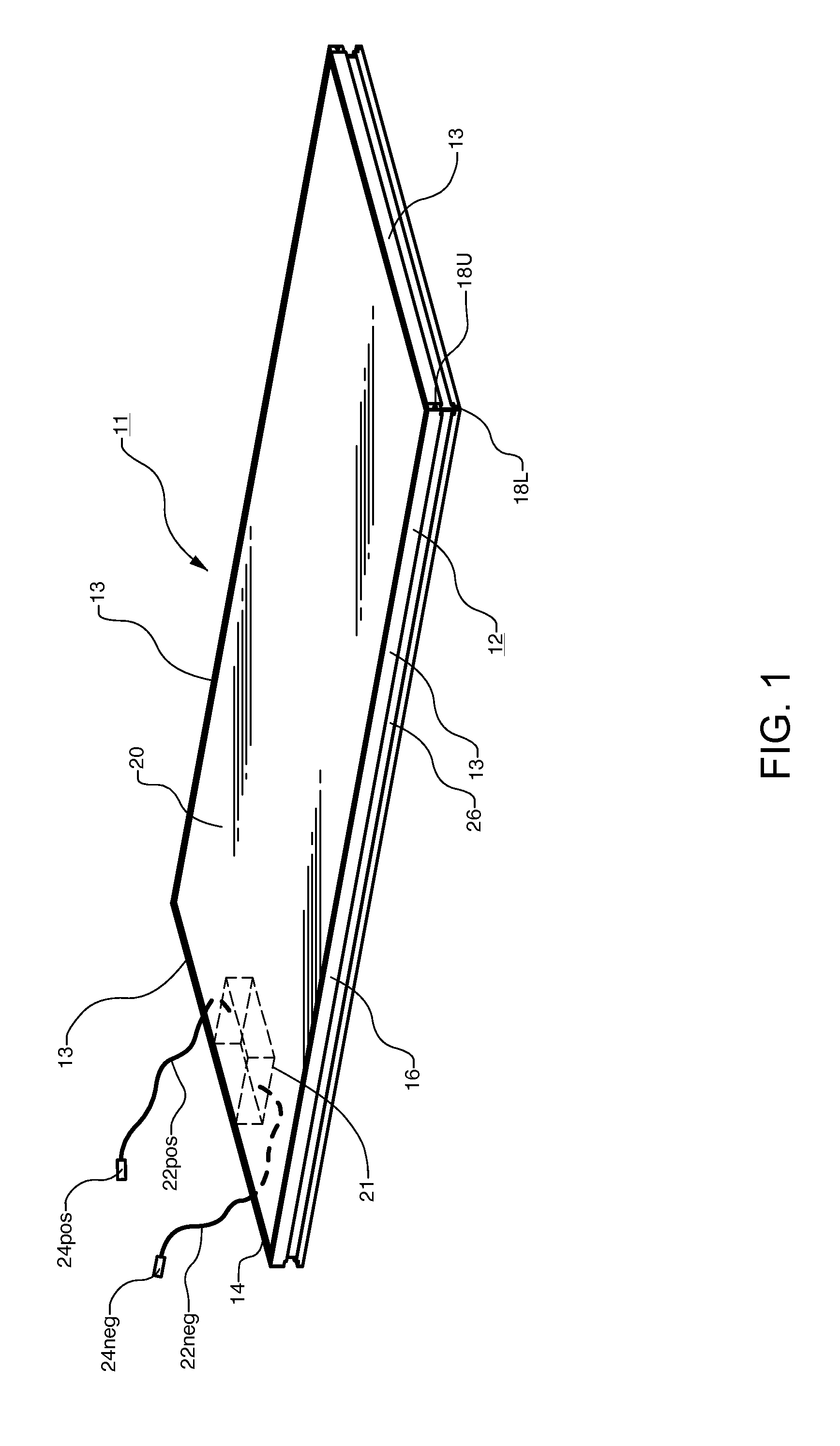
[0117]FIG. 31 is the same as FIG. 11 except that PV array 10 utilizes the framing and coupling system of the second embodiment. Brackets 132 are shown in the same locations except now they are connected to frames 212A, 212B, 212C, 212D via couplings 50j, thereby reducing total part count and installation time required for PV array 10. Series-parallel couplings 50b bridge the corner points where the four corners of PV modules 211A, 211B, 211C, 211D meet. For example, a coupling 50b is shown bridging a corner point 295 where four PV modules 211A, 211B, 211C, 211D meet. Parallel coupling portions 50bb interlock modules 211A, 211B and 211C, 211D while series coupling portion 162 interlocks modules 211B, 211D and 211A, 211C. Please note that a second series coupling portion between 211A, 211C is possible but not required since parallel coupling portions 50bb lock frame 212A to frame 212B and frame 212C to frame 212D along with series coupling portion 162.

[0118]Thus, the two axis parallel...

third embodiment

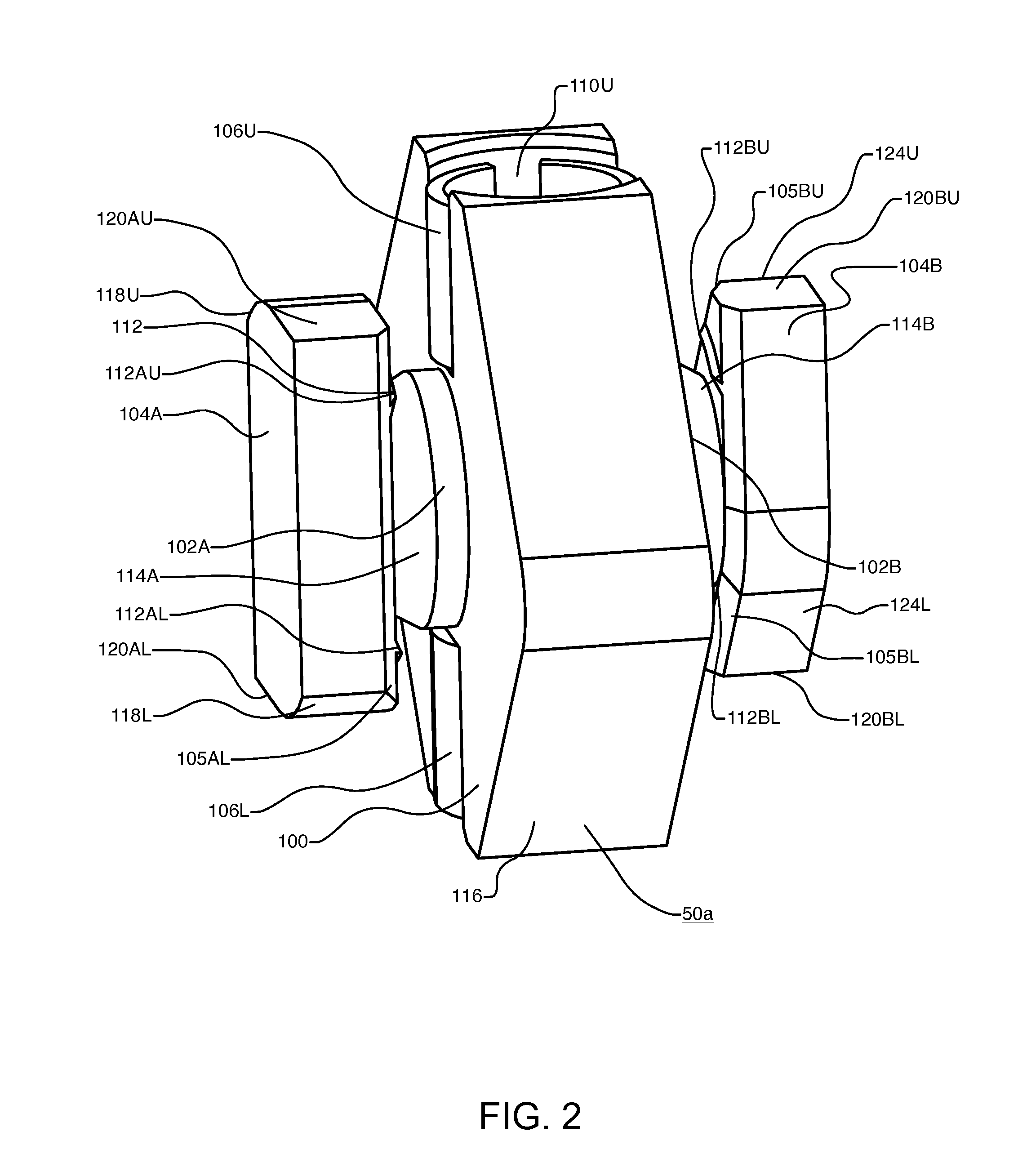
[0128]FIGS. 32-34 depict a third embodiment of the present invention. This embodiment is similar to the first embodiment described above except that the orientation of the coupling action of coupling 50a has been altered and a retaining element has been added. Instead of bearing against vertically oriented opposing surfaces on frame 12, a parallel coupling 50c is provided to bear against horizontally oriented opposing surfaces on frame 12.

[0129]FIG. 32 shows a perspective view of parallel coupling 50c which has been installed into slots 26A, 26B of two adjacent PV modules 11A, 11B but not fully tightened down. Frames 12A, 12B have been cut away so that coupling 50c shows in this view. FIG. 33 provides an exploded view of the two sides of a retainer portion 354L, 354R. FIG. 34 provides a cross-section view cut through two adjacent PV modules 11A, 11B which are coupled together with parallel coupling 50c. The cross section is cut partially through coupling 50c as indicated.

[0130]Refer...


PUM


Abstract

A photovoltaic (PV) module framing and coupling system enables the attachment of PV modules to a roof or other mounting surface without requiring the use of separate structural support members which attach directly to and span between multiple PV modules in a formed PV array. The apparatus provides a parallel coupling for securely interlocking the outside surfaces of parallel frame members together in a side to side arrangement to form an array with improved structural load distribution. The coupling may attach to a slot in the frame at substantially any position along the length of the frame thereby enabling the interconnection of adjacent PV modules along both an x and y axis. The apparatus may further provide a rotating portion and locking portion, mounting brackets for direct connection to a mounting surface, grounding teeth, and a twist-lock engagement means for interlocking and aligning PV modules in the array.

Description

CROSS REFERENCES[0001]The present application is a continuation of application Ser. No. 13 / 351,397, filed Jan. 17, 2012, which is a continuation of application Ser. No. 12 / 594,935 filed Oct. 6, 2009, now U.S. Pat. No. 8,109,048, issued Feb. 7, 2012. The foregoing applications are incorporated by reference in their entirety as if fully set forth herein.BACKGROUND[0002]Photovoltaic (PV) modules and related mounting hardware are well known and in widespread use. The most common mass-produced PV modules in use today include a laminated portion, or PV laminate, and a frame portion, and are designed specifically to convert light into electricity. The PV laminate portion is for encapsulating solar cells in a substantially flat, weather-tight envelope comprising a laminated construction of various layers including but not limited to glass, clear plastic, encapsulant material (like EVA), active photovoltaic material, interconnecting conductors between solar cells, and a protective backsheet ...

Claims


Application Information

Patent Timeline
Patent Type & Authority Applications(United States)
IPC IPC(8): H01L31/05H01L31/0203
CPCF24J2/5211Y10T403/70F24J2/5239F24J2/5245F24J2/5254F24J2/5258F24J2/526F24J2/5262F24J2/5264F24J2002/4669Y02B10/12Y02B10/20Y02E10/47Y02E10/50H02S20/00H02S20/23Y10T403/553F24J2/523F24S25/20F24S25/61F24S25/613F24S25/67F24S25/70F24S2025/02F24S25/10F24S25/16F24S25/632F24S25/636F24S25/65F24S2025/6006Y02B10/10H01L31/046H01L31/0508H02S30/00H02S30/10F16B5/10
Inventor WEST, JOHN R.
Owner SOLARCITY
Why Eureka
Try Eureka