Driving an electrowetting display device

a display device and electrowetting technology, applied in the direction of electric digital data processing, instruments, computing, etc., can solve the problems of electrowetting display to behave differently with an increase in applied voltage, display effect may be inconsistent, and display device hysteresis may be observed

Active Publication Date: 2012-10-11
LIQUAVISTA BV
View PDF5 Cites 14 Cited by
  • Summary
  • Abstract
  • Description
  • Claims
  • Application Information

AI Technical Summary

Benefits of technology

[0025]In other embodiments of the present invention, the display element comprises a second electrode, the method comprising applying the at least one pre-display signal level during the pre-display period to the second electrode and applying the at least one display signal level during the display period to the first electrode. These embodiments implement the present invention using two electrodes provided in the display element and adjacent to the surface. The pre-display signal level is applied to one electrode, this electrode for example being of a small area and located at a corner of the surface. The at least one display signal level for the display states in the display period is applied to the other electrode. Thus, electrode addressing for initiation and display state writing can be kept separate. This is less demanding for signal level sequences and frame rate timings for addressing the electrodes.
[0026]In exemplary embodiments, the method comprises applying a non-zero signal level to the second electrode throughout the display period. Thus, the display element may be initiated using a different electrode from the electrode receiving the at least one display signal level. This provides a simple method of addressing the display element.

Problems solved by technology

Hysteresis may be observed in electrowetting display devices.
Hysteresis causes the electrowetting display to behave differently with an increase of applied voltage, compared with a decreasing voltage.
Consequently, a display effect provided by the display may be inconsistent at a given voltage, depending on whether the applied voltage is reached from a lower or higher previous voltage.
This is problematic for a display requiring reliable display states.
Using AC requires twice the operating voltage than a direct current (DC) scheme; power consumption and operating costs are therefore higher, which is undesirable.

Method used


Image

  • Driving an electrowetting display device
  • Driving an electrowetting display device
  • Driving an electrowetting display device

Examples


Embodiment Construction

[0054]The entire contents of priority application GB 0918959.8 are incorporated by reference herein.

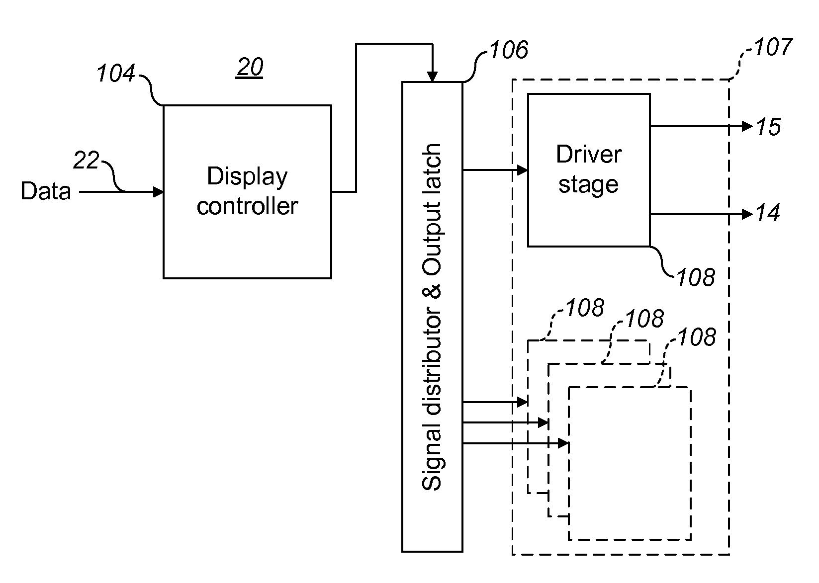
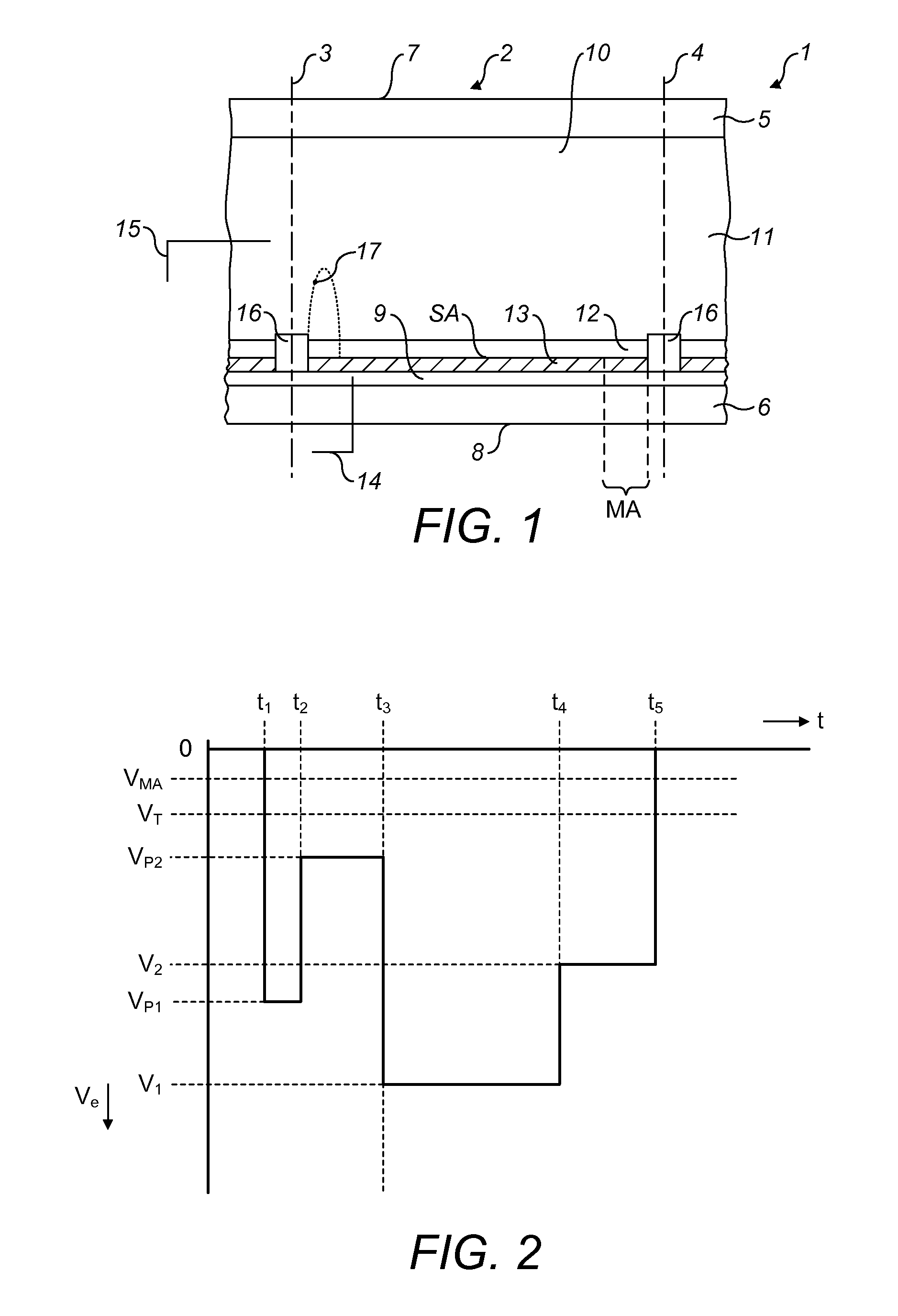
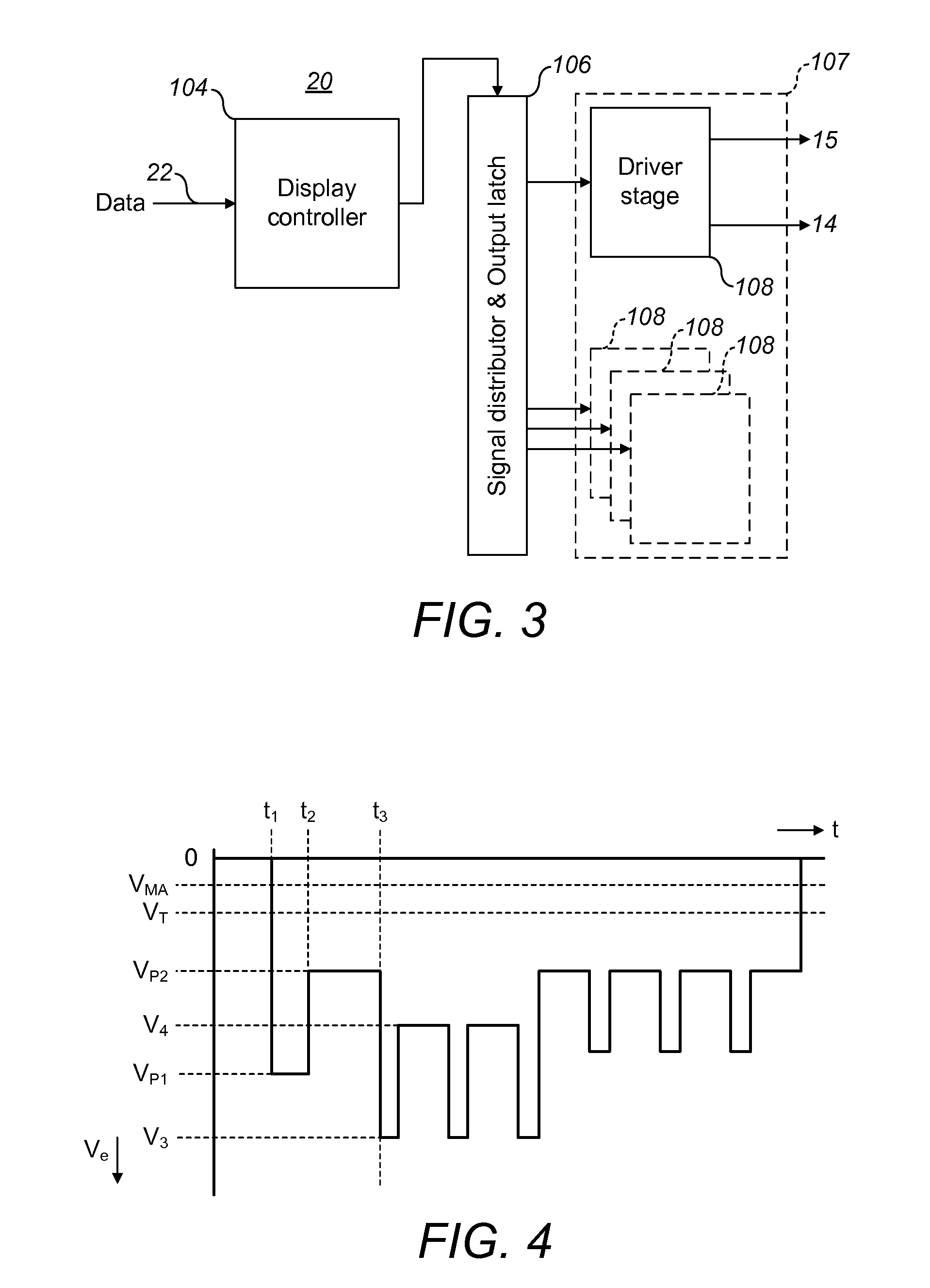
[0055]FIG. 1 shows a diagrammatic cross-section of an embodiment of an electrowetting display device 1. The display device includes a plurality of electrowetting display elements 2, one of which is shown in the Figure. The lateral extent of the element is indicated in the Figure by the two dashed lines 3, 4. The electrowetting elements comprise a first support plate 5 and a second support plate 6. The support plates may be separate parts of each electrowetting element, but the support plates are preferably shared in common by the plurality of electrowetting elements. The support plates may be made for instance of glass or polymer and may be rigid or flexible.

[0056]The display device has a viewing side 7 on which an image or display formed by the display device can be viewed and a rear side 8. The first support plate 5 faces the viewing side; the second support plate 6 faces the rear s...


PUM


Abstract

A method of driving an electrowetting display device that includes a display element having a cavity; a first fluid and a second fluid within the cavity, the first fluid being immiscible with the second fluid; a surface facing the cavity; and a first electrode. The display device includes a control system for applying a voltage to the first electrode to provide a display state in response to a signal level of the voltage, wherein the control system is arranged to configure the signal level throughout a display period such that the second fluid adjoins at least a minimum area of the surface, the minimum area being greater than a zero area. The method includes applying at least one display signal level during the display period, the at least one display signal level configured such that the first fluid and the second fluid adjoin the surface throughout the display period.

Description

FIELD OF THE INVENTION[0001]The present invention relates to a method of driving an electrowetting display device, a display device and a control system.BACKGROUND OF THE INVENTION[0002]Electrowetting display devices are known for example from PCT publication no. WO / 2003 / 071346. Hysteresis may be observed in electrowetting display devices. Hysteresis causes the electrowetting display to behave differently with an increase of applied voltage, compared with a decreasing voltage. Consequently, a display effect provided by the display may be inconsistent at a given voltage, depending on whether the applied voltage is reached from a lower or higher previous voltage. This is problematic for a display requiring reliable display states.[0003]The article “Gray Scales for Video Applications on Electrowetting Displays”, by R. van Dijk, B. J. Feenstra, R. A. Hayes, I. G. J. Camps, R. G. H. Boom, M. M. H Wagemans, A. Giraldo, B. v.d. Heijden, R. Los and H. Feil, Liquavista, ISSN0006-0966X / 06 / 370...

Claims


Application Information

Patent Timeline
Patent Type & Authority Applications(United States)
IPC IPC(8): G06F3/038
CPCG09G3/3433G09G2310/061G09G3/348G09G2320/0233G09G2320/066G09G2330/021
Inventor AUBERT, JODERCKX, HENRICUS PETRONELLA MARIASLACK, ANTHONY JOHNFEENSTRA, BOKKE JOHANNESBERGERON, NICHOLAS
Owner LIQUAVISTA BV
Why Eureka
Try Eureka