Method for Measuring Distances

Active Publication Date: 2012-10-11
RIEGL LASER MEASUREMENT SYSTEMS
View PDF8 Cites 100 Cited by
  • Summary
  • Abstract
  • Description
  • Claims
  • Application Information

AI Technical Summary

Benefits of technology

[0024]According to some embodiments of the invention, the method may also be used for laser scanning by using laser pulses as transmitted pulses which are directed progressively to

Problems solved by technology

Both cases may result in the situation that the next pulse is already transmitted before the reflection of the last pulse was received, so that the received pulses cannot be clearly mapped anymore to their respective transmitted pulse.
Laser scanners of modern design for instance offer pulse repetition rates of up to 400 kHz, which corresponds to a MTA zone size dmax of about 375 m. If this measuring distance is exceeded, the result of the measurement usually cannot be interpreted correctly, as the transmitted and receive

Method used


Image

  • Method for Measuring Distances
  • Method for Measuring Distances
  • Method for Measuring Distances

Examples


Embodiment Construction

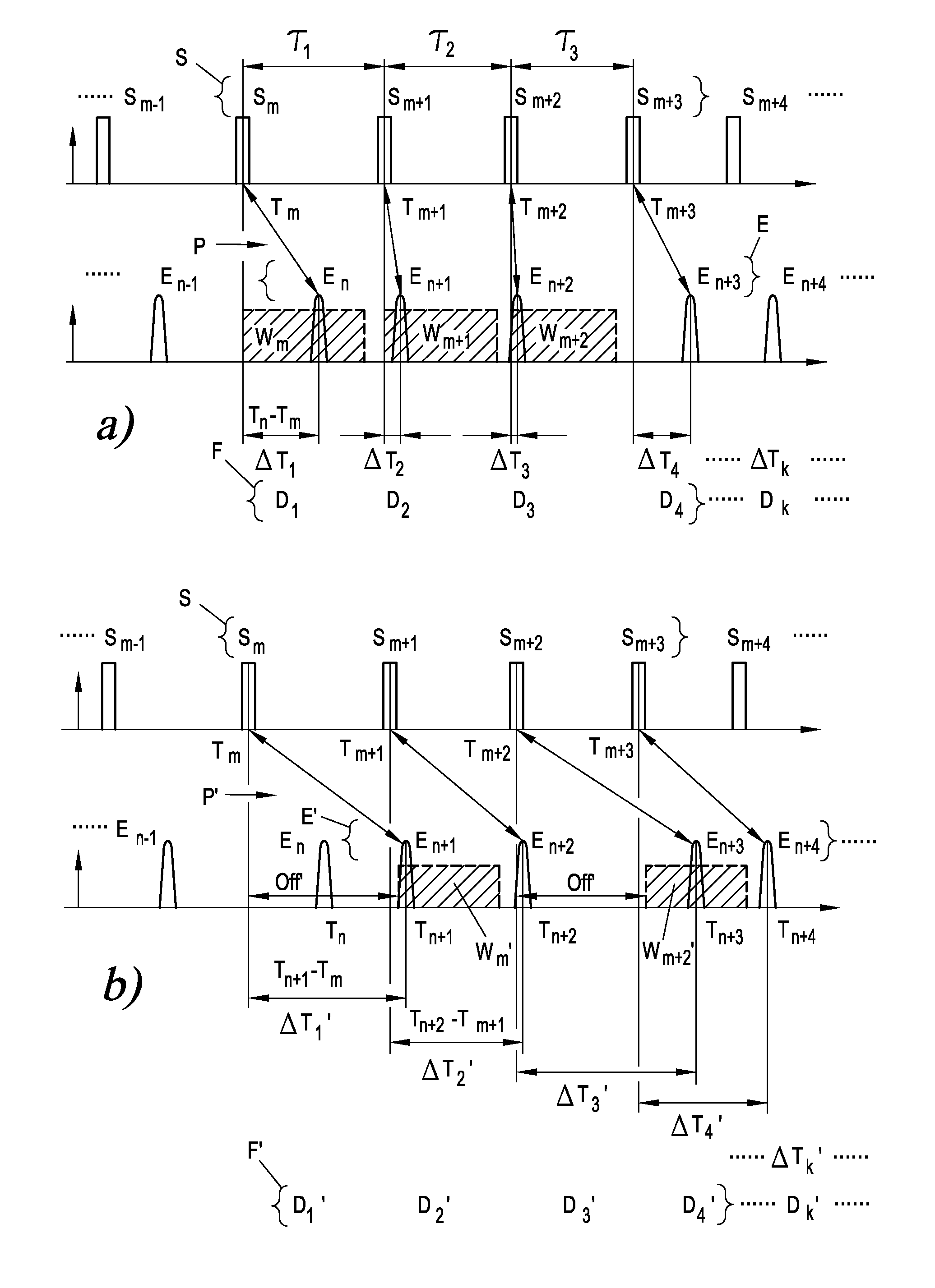
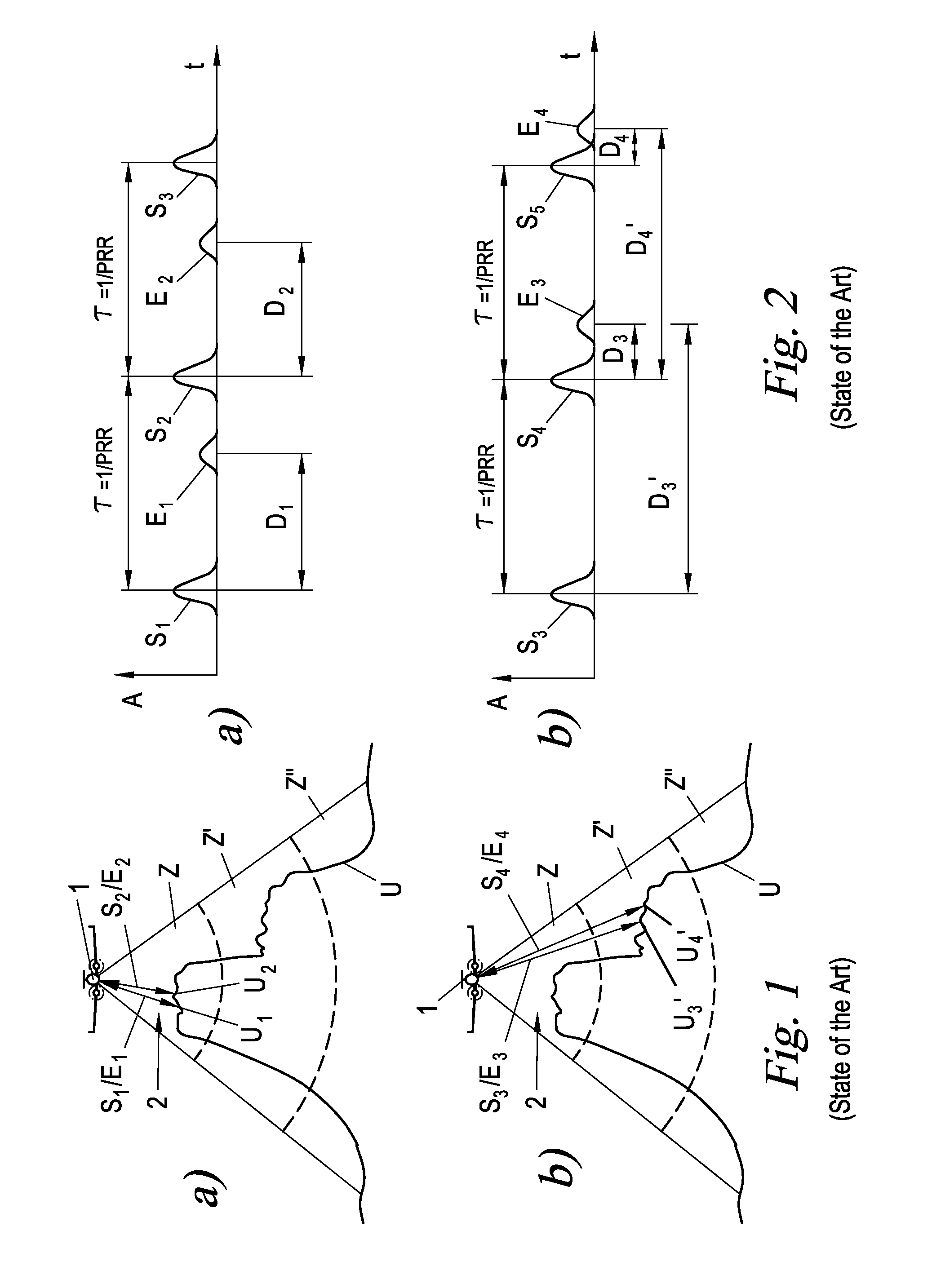
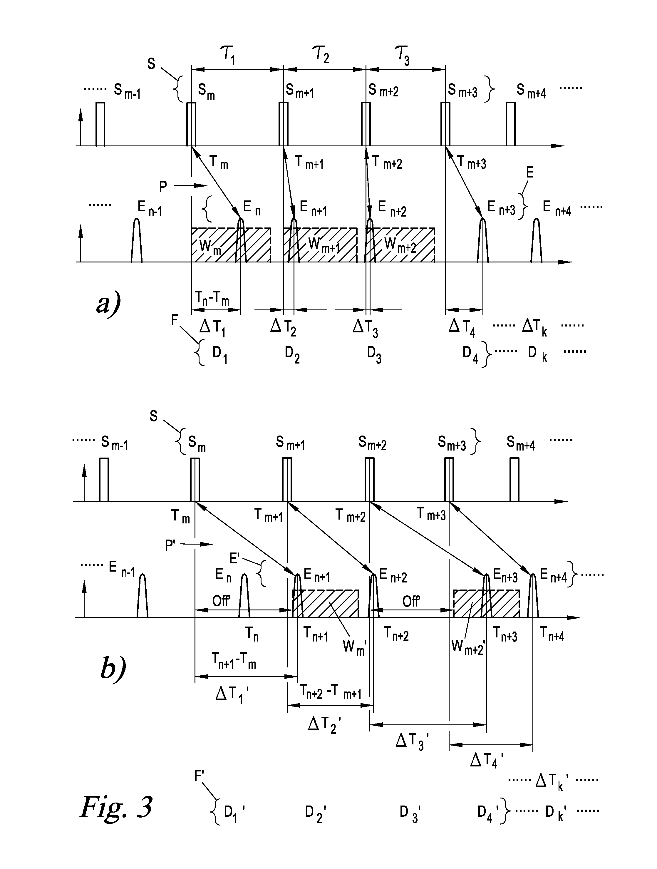
[0035]FIGS. 1 and 2 show the problem of pulse mapping of MTA zone-crossing measurement and scanning ranges and were already discussed at the outset. This problem is overcome by means of the method hereinafter described which is based on a signal-analytical evaluation of a large number of transmitted pulses S1, S2, S3, . . . , generally Sm, and received pulse E1, E2, E3, . . . , generally En.

[0036]The following method description specifically refers to laser pulses as transmitted and received pulses Sm, En. However, it is understood that the transmitted and received pulses Sm, En may be of any nature, for instance sound pulses in a sonar, light pulses in a time-of-flight camera (photonic mixing device, PMD), radar pulses in a radar range finder or scanner, electrical pulses in a line measuring instrument, etc., or just laser pulses in a laser range finder or scanner. Accordingly, the method described here can be generally applied to any kinds of pulse time-of-flight measuring methods...


PUM


Abstract

A method for measuring distances of targets by measuring the time of flight of pulses, in particular laser pulses, reflected on those targets, including the steps of; transmitting pulses having a pulse interval which varies according to a modulation signal as transmitted pulses, and concomitantly recording of reflected pulses as received pulses; determining a first series of distance measurement values from times of flight between transmitted pulses and those received pulses which are respectively received within a first time window following each transmitted pulse; determining at least a second series of distance measurement values from times of flight between transmitted pulses and those received pulses which are respectively received within a second time window following each transmitted pulse; and determining that series of distance measurement values which is least affected by the modulation signal as result of the distance measurement.

Description

CROSS-REFERENCE TO RELATED APPLICATION(S)[0001]This application claims priority to Austrian Patent Application No. A 494 / 2011 filed on Apr. 7, 2011, the contents of which is hereby expressly incorporated by reference.[0002]Copending is International Patent Application No. PCT / AT 2011 / 000377 filed on Sep. 15, 2011.FIELD OF THE INVENTION[0003]The present invention relates to a method for measuring distances of targets by measuring the time of flight of pulses reflected on those targets.[0004]The pulses may be of any kind, e.g. light pulses, in particular laser pulses, radio pulses, in particular radar pulses, sound pulses or the like.[0005]The present invention further relates to a method for laser scanning by progressively directing laser pulses to different targets.BACKGROUND OF THE INVENTION[0006]Modern pulse time-of-flight distance measuring apparatus such as laser range finders or laser scanners work at a high pulse power over large distances and / or at a high pulse repetition rat...

Claims


Application Information

Patent Timeline
IPC IPC(8): G01C3/08G01S17/18
CPCG01S17/107G01S7/487G01S17/18
Inventor RIEGER, PETERULLRICH, ANDREAS
Owner RIEGL LASER MEASUREMENT SYSTEMS
Why Eureka
Try Eureka