
Method for operating a jamming laser in a DIRCM system in a manner that is safe for eyes

a laser and dircm technology, applied in the direction of distance measurement, instruments, weapons, etc., can solve the problems of laser safety problems, increased civilian aircraft, and increased military and civilian aircraft at risk of surface-to-air missile attacks (sams)

Inactive Publication Date: 2014-01-21
HENSOLDT SENSORS GMBH
View PDF12 Cites 0 Cited by
  • Summary
  • Abstract
  • Description
  • Claims
  • Application Information

AI Technical Summary

Benefits of technology

The present invention provides a method for safely using a DIRCM system without causing any restrictions on its use due to safety concerns. The method uses high-intensity jamming radiation to protect the system from infrared radiation from the aircraft being protected, preventing it from being easily targeted by a SAM. The method also ensures that the DIRCM system operates efficiently and at low costs. The invention has several advantages, such as minimizing restrictions on use and keeping equipment costs low. Overall, the invention provides a safer and cost-effective way to use a DIRCM system for protecting aircraft.

Problems solved by technology

Military and, increasingly civilian aircraft, are at risk of attack by surface-to-air missiles (SAMs).
Using jamming intensities that are too low is counterproductive, as it makes it easier for the oncoming SAM to locate its target.
The high laser intensities required result in a laser safety problem.
This leads to restrictions on the licensing and use of a DIRCM system, particularly in situations such as take-off and landing, when the potential threat is greatest and protection from a DIRCM system is therefore most important.
The disadvantage of this method is that below an altitude corresponding to the NOHD or ENOHD, the aircraft is left unprotected by a DIRCM, right at the very moment when the threat is greatest.
However, this approach is not acceptable for civilian applications and licenses.
Because many military aircraft are now also licensed and used for civilian purposes, this approach represents a major disadvantage for military aircraft too.
Furthermore, the equipment costs are to be kept low.
However, the cost of this is the restriction that the laser emission and therefore also possible engagement with an attacking SAM may have to be suspended for laser safety reasons.
At even lower altitudes, the limit for energy 2 will also be around 0, so that no combat is possible for laser protection reasons.

Method used


Image

  • Method for operating a jamming laser in a DIRCM system in a manner that is safe for eyes
  • Method for operating a jamming laser in a DIRCM system in a manner that is safe for eyes

Examples


Embodiment Construction

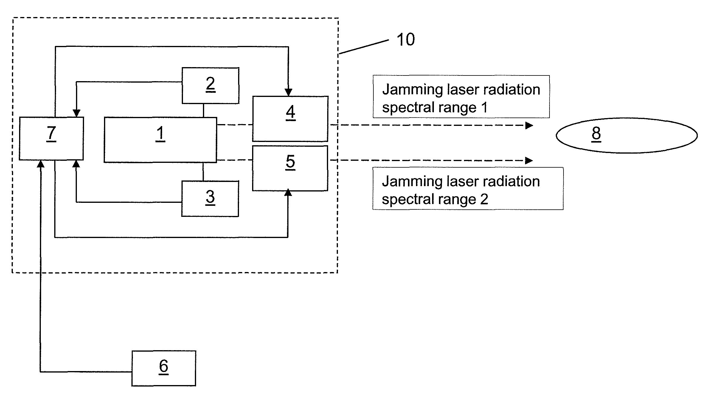
[0035]The invention is explained in greater detail using an exemplary embodiment with reference to a FIGURE. This shows a schematic representation of the components of a DIRCM system 10 relevant to the implementation of the method according to the invention. The FIGURE shows an embodiment in which a distinction is made between the two spectral ranges 1 and 2.

[0036]The DIRCM system shown comprises the jamming laser 1 for engaging an oncoming SAM 8. The altitude above ground is determined continuously, e.g. by a radar altimeter 6. The measuring devices 2 and 3 continuously determine the energy radiated in spectral range 1 and 2 since the start of combat. Using this data, the control unit 7 then generates cut-off signals for the two locking devices 4 and 5 to switch off the laser emission in the spectral range 1 and 2 of the laser, so that the maximum permitted radiation on the ground according to EN 60825-1 is at no time exceeded.

[0037]The switch-off in this case is performed by the c...


PUM


Abstract

A method for operating a jamming laser in a DIRCM system on board an aircraft in a manner that is safe for eyes. The energy radiated by the jamming laser since the start of combat is determined, depending on the aircraft's flight condition, a limit is determined for the permitted energy radiation, where the limit corresponds to a laser protection distance to be observed for this flight condition, and when the limit is reached, radiation is suppressed.

Description

BACKGROUND AND SUMMARY OF THE INVENTION[0001]The invention relates to a method for operating a jamming laser in a DIRCM system on board an aircraft in a manner that is safe for eyes.[0002]Military and, increasingly civilian aircraft, are at risk of attack by surface-to-air missiles (SAMs). The most common SAMs are so-called MANPADS (Man-Portable Air Defense Systems) with a seeker head operating in the infrared spectral range.[0003]One possible countermeasure is the emission of directed infrared laser radiation modulated with a suitable jamming sequence against the oncoming SAM, in order to jam its seeker head and cause it to miss its target. Systems of this kind are known as DIRCM (Directional Infrared Countermeasures) systems and are disclosed, for example, in German Patent Document DE 4402855 A1 and U.S. Pat. No. 6,369,885 B1.[0004]In order for it to be effective, the intensity of the jamming radiation generated by the DIRCM system must be significantly higher than the infrared ra...

Claims


Application Information

Patent Timeline
Patent Type & Authority Patents(United States)
IPC IPC(8): G01C3/08
CPCG01S7/495H04K3/41F41H13/0056H04K2203/22H04K3/43H04K2203/14
Inventor SCHERBARTH, STEFAN
Owner HENSOLDT SENSORS GMBH
Learn More