
Transaction Model With Structural And Behavioral Description Of Complex Transactions

a transaction model and transaction model technology, applied in the field of monitoring software, can solve the problems of time-consuming and difficult diagnosis of problems

Inactive Publication Date: 2012-10-11
CA TECH INC
View PDF16 Cites 70 Cited by
  • Summary
  • Abstract
  • Description
  • Claims
  • Application Information

AI Technical Summary

Benefits of technology

[0010]In another embodiment, at least one tangible, non-transitory processor-readable storage device having processor-readable software embodied thereon is provided for programming at least one processor to perform a method for tracking flows through at least one application. The method includes: (a) providing vertex records which identify software components which are invoked during transactions involving the at least one application, (b) providing edge records which identify calls between the software components, the edge records are linked to the vertex records, (c) providing transaction records which identify the transactions, and which are linked to the edge records, the transaction records represent a transaction hierarchy, the transaction hierarchy comprising the transactions at one level of the transaction hierarchy and one or more groupings of the transactions at a first higher level of the transaction hierarchy, and (d) providing a directed graph in a user interface display, the directed graph includes vertexes based on the vertex records and edges based on the edge records, and the vertexes are arranged according to the transaction hierarchy.

Problems solved by technology

However, diagnosis of problems continues to be difficult and time-consuming.

Method used


Image

  • Transaction Model With Structural And Behavioral Description Of Complex Transactions
  • Transaction Model With Structural And Behavioral Description Of Complex Transactions
  • Transaction Model With Structural And Behavioral Description Of Complex Transactions

Examples


Embodiment Construction

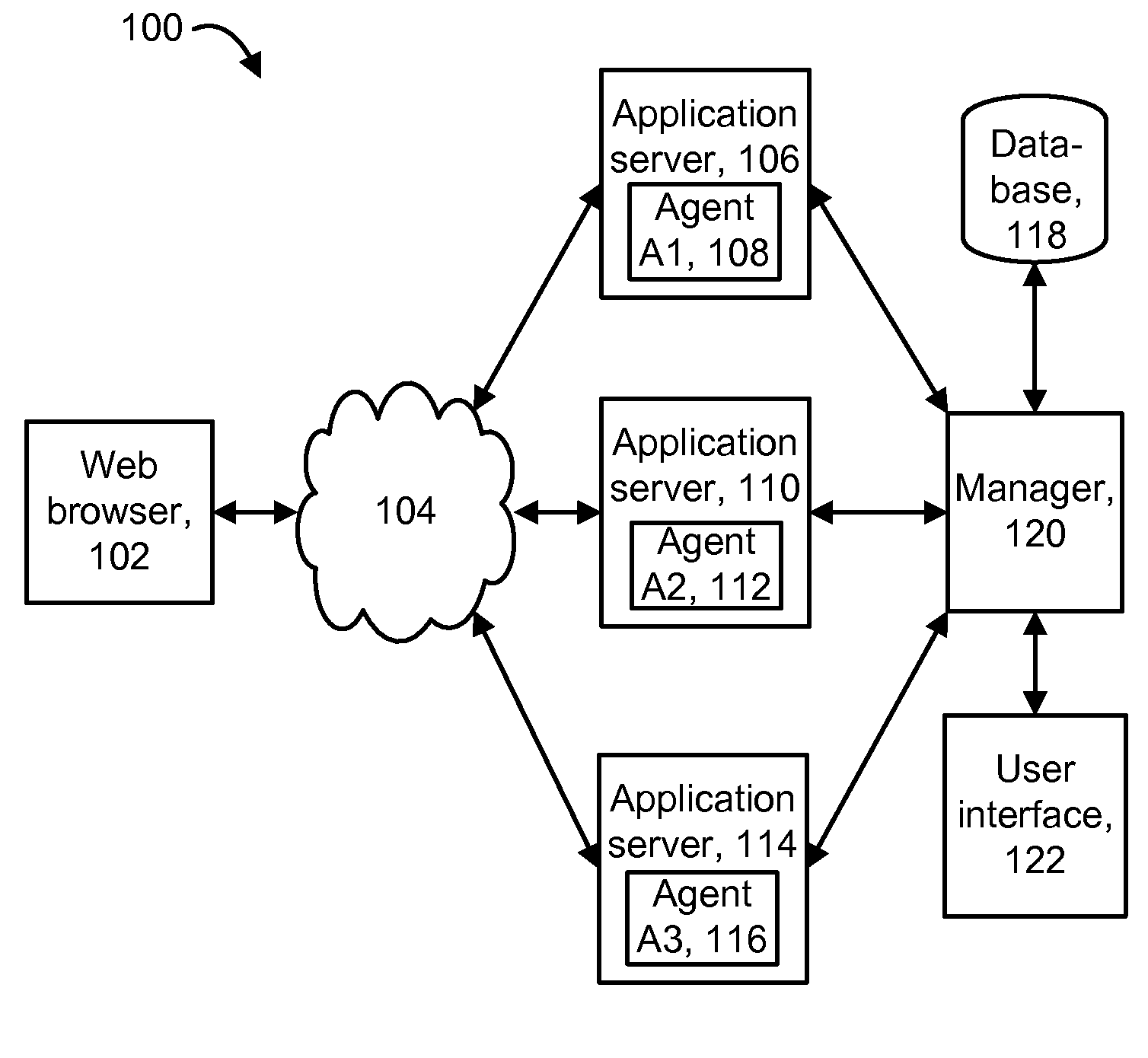
[0058]The present invention provides a method for diagnosing problems in a computer system by tracking flows through at least one application of the computer system.

[0059]When a Business Transaction or application is failing, the provider wants to know what exactly is going wrong and why. A Business Transaction can represent a task from a client perspective, such as logging into a web site, ordering an item, and so forth. Sometimes the problem is general—the transaction fails every time—and sometimes it is more specific. For instance, the transaction may fail only when a certain user attempts it, or when a certain type of item is requested. Determining whether the problem is general or specific can be challenging, and isolating the source of the problem is more so.

[0060]Different diagnostic tools are provided for the general and specific cases. For example, a directed graph (also referred to as a triage map or application map) can be used to address the general case, as it aggregate...


PUM


Abstract

A model is used to provide a user interface to track flows through at least one application of a computer system. The model relates the structural aspects of the at least one application to a behavioral model such as a business transaction hierarchy. The structural part of the model includes linked Vertex and Edge records. Vertex records for different instances of a component can be aggregated to provide a single vertex or node for display in a user interface. A Vertex record is linked to an Agent record and a Metric Path record. The Edge records identify tail and head components of a call. A set of Edge records can be associated with a Transaction record in the behavioral part of the model. A Transaction record can be associated with a Business Transaction Record, and a Business Transaction record can be associated with a Business Service Record.

Description

BACKGROUND OF THE INVENTION[0001]1. Field of the Invention[0002]The present invention is directed to technology for monitoring software in a computing environment.[0003]2. Description of the Related Art[0004]The growing presence of the Internet as well as other computer networks such as intranets and extranets has brought many new applications in e-commerce, education and other areas. Organizations increasingly rely on such applications to carry out their business or other objectives, and devote considerable resources to ensuring that they perform as expected. To this end, various application management techniques have been developed.[0005]One approach involves monitoring the infrastructure of the application by collecting application runtime data regarding the individual software components that are invoked in the application. This approach can use agents that essentially live in the system being monitored. For example, using instrumentation of the software, a thread or process can...

Claims


Application Information

Patent Timeline
Patent Type & Authority Applications(United States)
IPC IPC(8): G06Q10/00
CPCG06Q10/06
Inventor UMANSKY, VLADIMIRBASAK, INDRANILSAWANT, ABHIJITBLACKWELL, AARON KENNETHCOBB, JEFFREY R.
Owner CA TECH INC
Learn More