Multi-cylinder rotary compressor and refrigeration cycle apparatus

a rotary compressor and refrigeration cycle technology, applied in the direction of lighting and heating apparatus, positive displacement liquid engine, liquid fuel engine, etc., can solve the problems of deformation of the vane groove precision, and lower compression performance, so as to reduce the machining accuracy. , the effect of shortening the life of the broach blad

Active Publication Date: 2012-10-18
TOSHIBA CARRIER CORP
View PDF2 Cites 16 Cited by
  • Summary
  • Abstract
  • Description
  • Claims
  • Application Information

AI Technical Summary

Benefits of technology

[0009]In the above enclosed compressor, an oil stagnant portion of lubricating oil is formed at an inner bottom of a well-closed container and almost all of a compression mechanism unit is soaked in the lubricating oil. The oil communication hole is open to the oil stagnant portion and lubricating oil is guided to the oil groove via the oil communication hole to oil the sliding contact surface between the vane groove and the vane. If the second vane chamber has a sealed structure, smoothness is ensured for reciprocating movement of the vane.
[0013]Working on a vane groove after an oil groove in a circular shape is provided can be considered, but a worked portion and a non-worked portion arise in a broach blade due to the presence of the oil groove. The shape of the broach blade is thereby deformed, leading to decreased machining accuracy and an extremely shorter life of the broach blade.
[0014]The present invention is made in view of the above circumstances and an object thereof is to provide a multi-cylinder rotary compressor capable of providing high compression performance by ensuring smoothness of reciprocating movement of the vane on the side of performing a resting cylinder operation on the assumption that the multi-cylinder rotary compressor includes two cylinders and the compression capacity can be switched and a refrigeration cycle apparatus capable of improving the efficiency of the refrigeration cycle by including the multi-cylinder rotary compressor.
[0015]To achieve the above object, a multi-cylinder rotary compressor according to the present invention contains an electric motor unit and a compression mechanism unit in a well-closed container and causes lubricating oil to stagnate at the bottom of the well-closed container.

Problems solved by technology

If the full-capacity operation is switched to the compression operation in this state, the rear-side end of the vane needs to reciprocate in the lubricating oil in the second vane chamber, leading to lower compression performance due to lack of smoothness of movement.
An oil groove is normally obtained by broaching, but if an oil groove is additionally worked on after a vane groove is worked on, the vane groove may be deformed or burrs, protrusions or the like arises while the vane groove is worked on, leading to lower performance / reliability due to degraded precision of the width of the vane groove.

Method used


Image

  • Multi-cylinder rotary compressor and refrigeration cycle apparatus
  • Multi-cylinder rotary compressor and refrigeration cycle apparatus
  • Multi-cylinder rotary compressor and refrigeration cycle apparatus

Examples


Embodiment Construction

[0026]An embodiment of the present invention will be described below based on drawings.

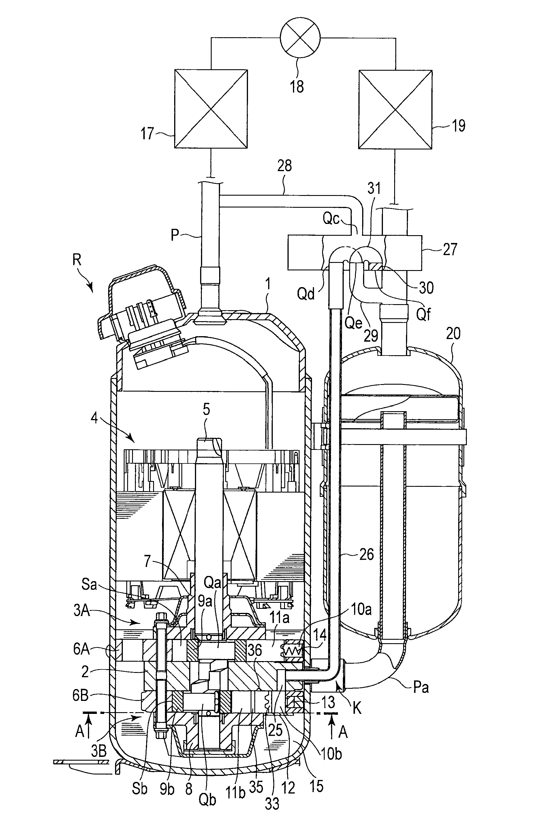
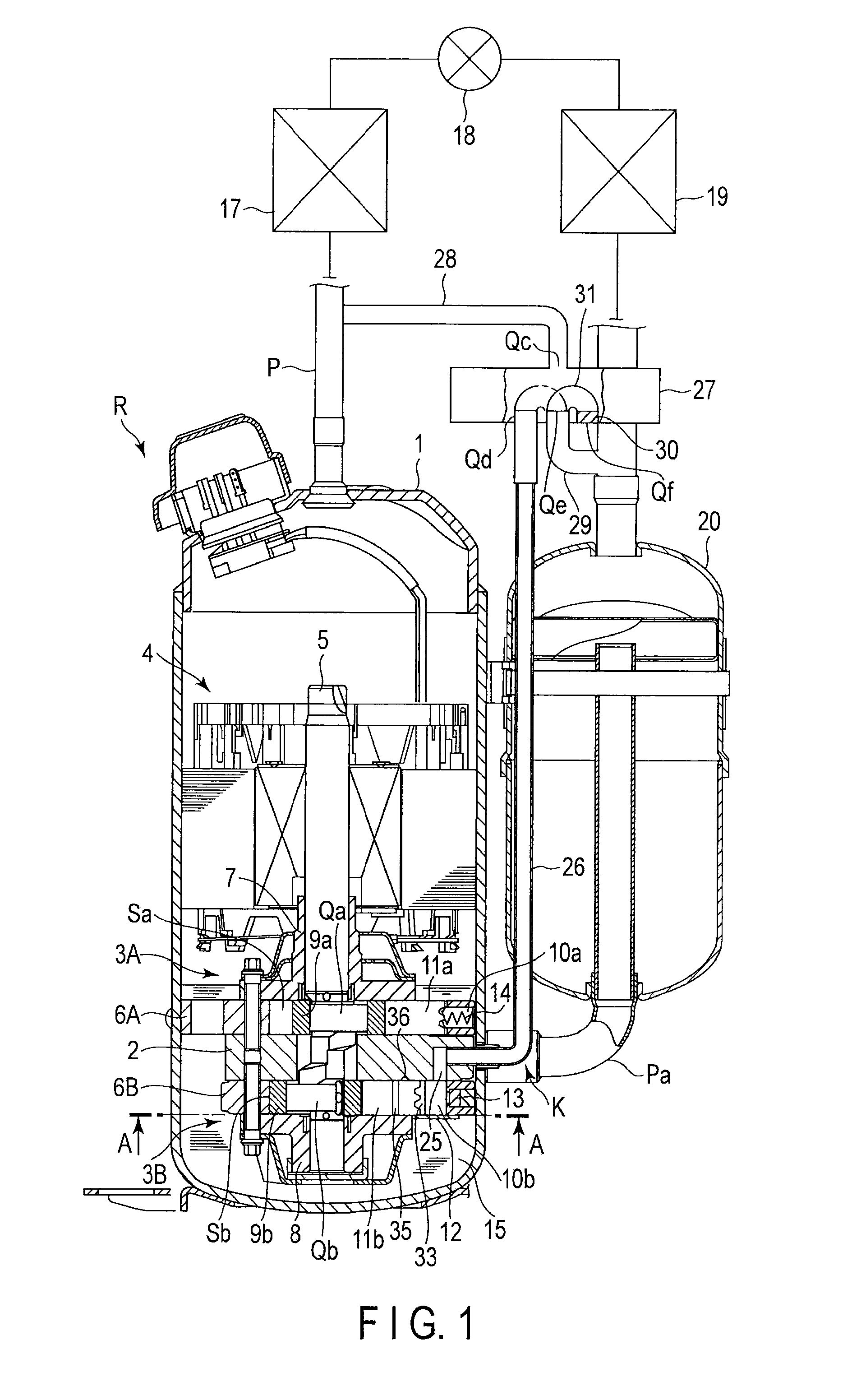
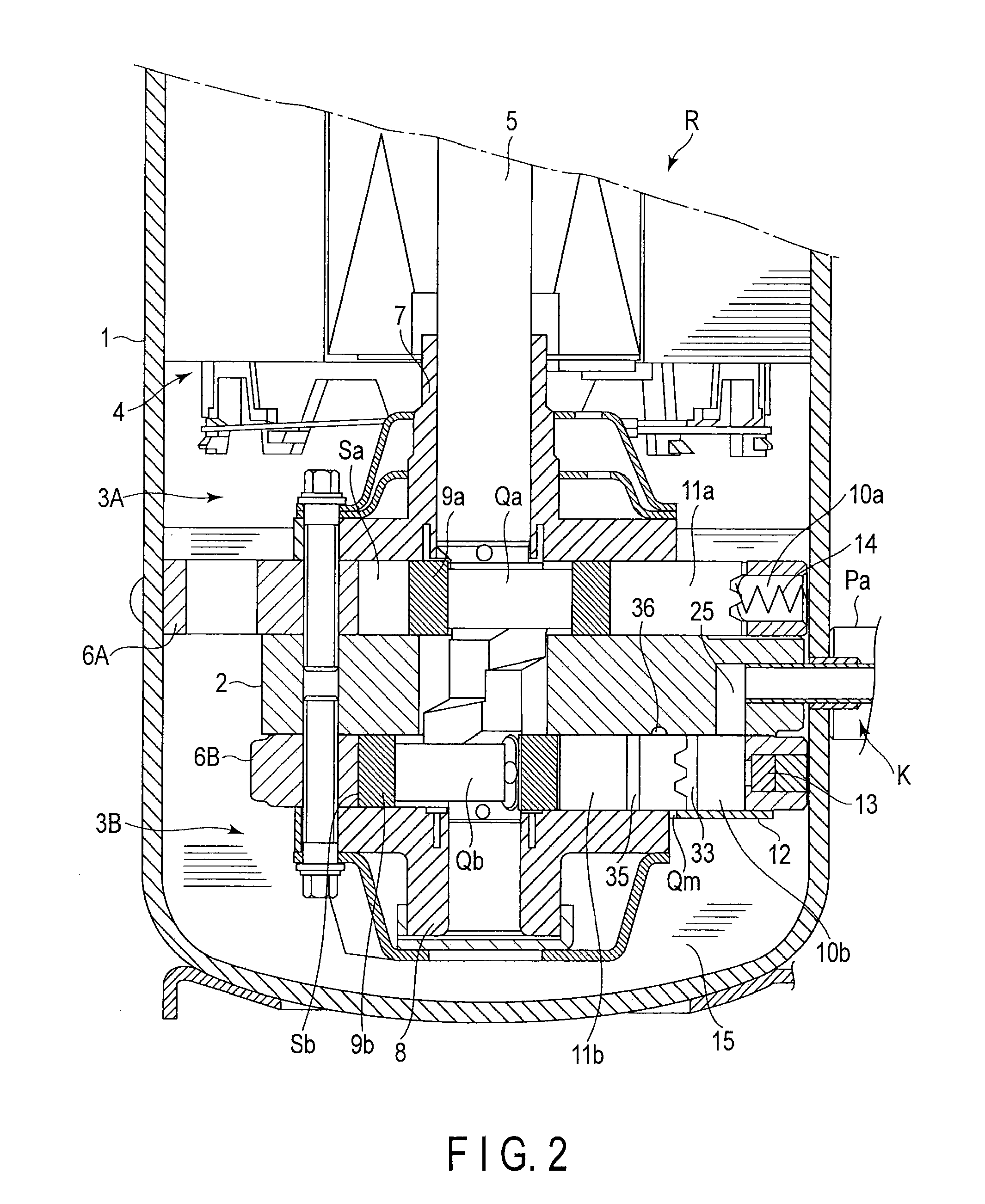
[0027]FIG. 1 shows a section structure of an outline multi-cylinder rotary compressor R and a refrigeration cycle configuration of a refrigeration cycle apparatus including the multi-cylinder rotary compressor R. FIG. 2 is a longitudinal sectional view showing the multi-cylinder rotary compressor R by enlarging a portion thereof (some parts have, though described, no reference number attached thereto to avoid complicatedness of drawings and this also applies below).

[0028]First, the multi-cylinder rotary compressor R will be described. Reference number 1 is a well-closed container and a first compression mechanism unit 3A and a second compression mechanism unit 3B are provided in a lower part of the well-closed container 1 via an intermediate partition plate 2 and an electric motor unit 4 is provided in an upper part thereof. These first compression mechanism unit 3A and second compression mechanis...


PUM


Abstract

A compression mechanism units include cylinder chambers into which a low-pressure gas is introduced, vanes contained in a vane groove, and a spring body that always causes compression operation in the cylinder chambers by providing an elastic force to a rear-end portion of one of the vanes, includes a pressure switching mechanism that switches to perform compression operation by guiding a high-pressure gas / not to perform the compression operation by guiding a low-pressure gas, is provided with a lubricating oil communication path communicatively connecting a oiling groove and a oil stagnant portion, and opposing the oiling groove to a portion other than the lubricating oil communication path when the vanes are in a top dead center position.

Description

CROSS REFERENCE TO RELATED APPLICATIONS[0001]This application is a Continuation Application of PCT Application No. PCT / JP2010 / 065471, filed Sep. 9, 2010 and based upon and claiming the benefit of priority from prior Japanese Patent Application No. 2009-211100, filed Sep. 11, 2009, the entire contents of all of which are incorporated herein by reference.BACKGROUND OF THE INVENTION[0002]1. Field of the Invention[0003]The present invention relates to a multi-cylinder rotary compressor capable of switching compression capacities and a refrigeration cycle apparatus that configures a refrigeration cycle by including the multi-cylinder rotary compressor.[0004]2. Description of the Related Art[0005]In a refrigeration cycle apparatus, multi-cylinder rotary compressors including a plurality of cylinder chambers (mainly two) in a compression mechanism unit are frequently used. Such a kind of compressor is advantageous if it is possible to carry out switching between the so-called full-capacity...

Claims


Application Information

Patent Timeline
Patent Type & Authority Applications(United States)
IPC IPC(8): F04C18/00F25B1/00
CPCF01C21/0845F01C21/0863F04C29/02F04C23/001F04C23/008F04C18/3564
Inventor HIRAYAMA, TAKUYA
Owner TOSHIBA CARRIER CORP
Why Eureka
Try Eureka