Unlock instant, AI-driven research and patent intelligence for your innovation.

Joystick device

a technology of a joystick and a rotatable cylinder, which is applied in the direction of mechanical control devices, manual control with a single controlling member, instruments, etc., can solve the problems of limited position for arranging the magnetic sensor, difficult to say that the configuration has a high degree of design freedom, and achieve the effect of enhancing the degree of design freedom

Active Publication Date: 2012-10-18
TOYO DENSO
View PDF8 Cites 19 Cited by
  • Summary
  • Abstract
  • Description
  • Claims
  • Application Information

AI Technical Summary

Benefits of technology

The present invention provides a joystick device with a less number of necessary magnets while enhancing the degree of design freedom for arranging a magnetic sensor in the axial direction of a rotatable cylinder for detecting the rotation position of the cylinder. The device includes an operation shaft, a rotatable cylinder, and a case. A driven gear is provided around the outer periphery of the rotatable cylinder, and a rotary body is rotatably supported by the case at a side of the rotatable cylinder. The rotary body has a smaller diameter than the rotatable cylinder and is rotatably supported by the case at a side of the rotatable cylinder. The device also includes a magnetic sensor provided in the case in such a way as to face the other end portion of the rotatable cylinder. The magnetic sensor detects the rotation position of the rotatable cylinder based on positional change relative to the magnets along with the rotation of the rotary body. The invention reduces the necessary number of magnets and enhances the degree of freedom for the arrangement of the magnetic sensor.

Problems solved by technology

For this reason, a space for arranging the light-emitting element or the light-receiving element needs to be secured inside the rotatable cylinder on the other end side, and thus there arises a limitation on arrangement of the other components to be arranged in the other end portion of the rotatable cylinder.
With the above-described configuration in which the magnetic sensor is arranged directly facing the other end portion of the rotatable cylinder, however, a position for arranging the magnetic sensor is limited in an axial direction of the rotatable cylinder.
Thus, it is hard to say that the configuration has a high degree of design freedom, and the rotatable cylinder requires a large number of magnets.

Method used


Image

  • Joystick device
  • Joystick device
  • Joystick device

Examples


Embodiment Construction

[0024]An embodiment of the present invention will be described below while referring to the attached FIGS. 1 to 11.

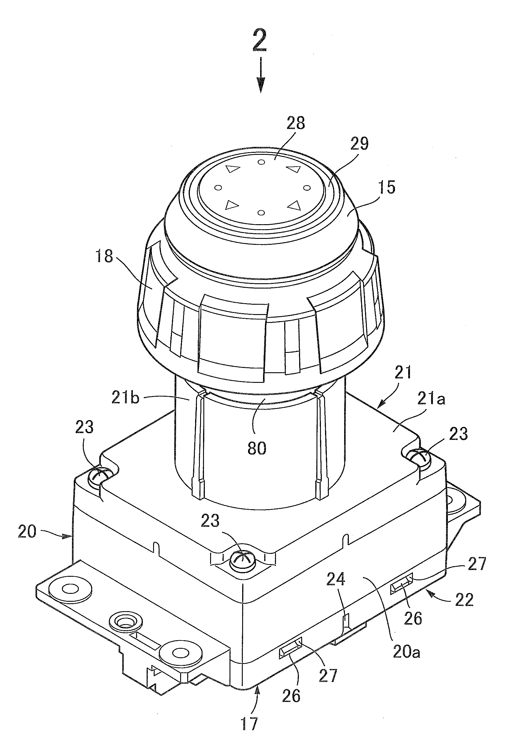
[0025]First, FIGS. 1 to 3 show a joystick device used for a cursor operation on a screen of a car navigation system, for example. The joystick device includes an operation knob 15, an operation shaft 16, a case 17, and a dial knob 18. The operation shaft 16 is coupled to the operation knob 15 on its one end. The case 17 tiltably supports the operation shaft 16. The dial knob 18 is arranged at a position adjacent to the operation knob 15 to be rotatable around an axis of the operation shaft 16.

[0026]Referring to FIG. 4 together, the case 17 includes a case main body 20, a first lid member 21, and a second lid member 22. The first lid member 21 is fastened to the case main body 20 with multiple screw members 23. The second lid member 22 is joined to the case main body 20 on the opposite side of the case main body 20 from the first lid member 21.

[0027]The case main body 20...


PUM


Abstract

In a joystick device, a rotation position detector for detecting a rotation position of a rotatable cylinder having one end coupled with a dial knob is provided between the cylinder and a case. The detector includes a drive gear provided around the cylinder, a rotary body which has a driven gear provided around its outer periphery and is in mesh with the drive gear, multiple magnets provided on the rotary body, and a magnetic sensor provided in the case to face one end portion of the rotary body to detect the rotation position of the cylinder based on positional change relative to the magnets along with rotation of the rotary body. Such arrangement enhances the degree of design freedom for arranging a magnetic sensor in the axial direction of the cylinder in detecting a rotation position of the cylinder by the sensor and reduces a necessary number of magnets.

Description

BACKGROUND OF THE INVENTION[0001]1. Field of the Invention[0002]The present invention relates to a joystick device in which an operation shaft having one end to which an operation knob is coupled is supported by a case to be tiltable from a neutral position about a tilting center set on an axis of the operation shaft, a cylindrical rotatable cylinder having one end joined to a dial knob and surrounding the operation shaft is supported by the case to be rotatable about the axis, and rotation position detection means for detecting a rotation position of the rotatable cylinder is provided between the other end portion of the rotatable cylinder and the case.[0003]2. Description of the Related Art[0004]Such a joystick device is already known from, for example, Japanese Patent Application Laid-open No. 2005-122290.[0005]Meanwhile, in the joystick device disclosed in Japanese Patent Application Laid-open No. 2005-122290, the rotation position detection means for detecting the rotation posi...

Claims


Application Information

Patent Timeline
Patent Type & Authority Applications(United States)
IPC IPC(8): G05G1/12
CPCG05G1/08Y10T74/20492G05G9/047
Inventor TERAO, TAKANORINAKAGAWA, SATORU
Owner TOYO DENSO