Valve handle for butterfly valve for bulk commodity hopper with tee

a butterfly valve and bulk commodity technology, applied in the field of valve handles, can solve the problems of inconvenient access to the valve for the purpose of opening and closing such valves, poor wear characteristics of the valve handle constructed of such lighter weight materials, and poor wear characteristics of the valve handle. the effect of convenient striking

a butterfly valve and bulk commodity technology, applied in the field of valve handles, can solve the problems of inconvenient access to the valve for the purpose of opening and closing such valves, poor wear characteristics of the valve handle constructed of such lighter weight materials, and poor wear characteristics of the valve handle. the effect of convenient striking

US20120261602A1Active Publication Date: 2012-10-18BULK TANK

Image

  • Valve handle for butterfly valve for bulk commodity hopper with tee
  • Valve handle for butterfly valve for bulk commodity hopper with tee
  • Valve handle for butterfly valve for bulk commodity hopper with tee

Examples


Embodiment Construction

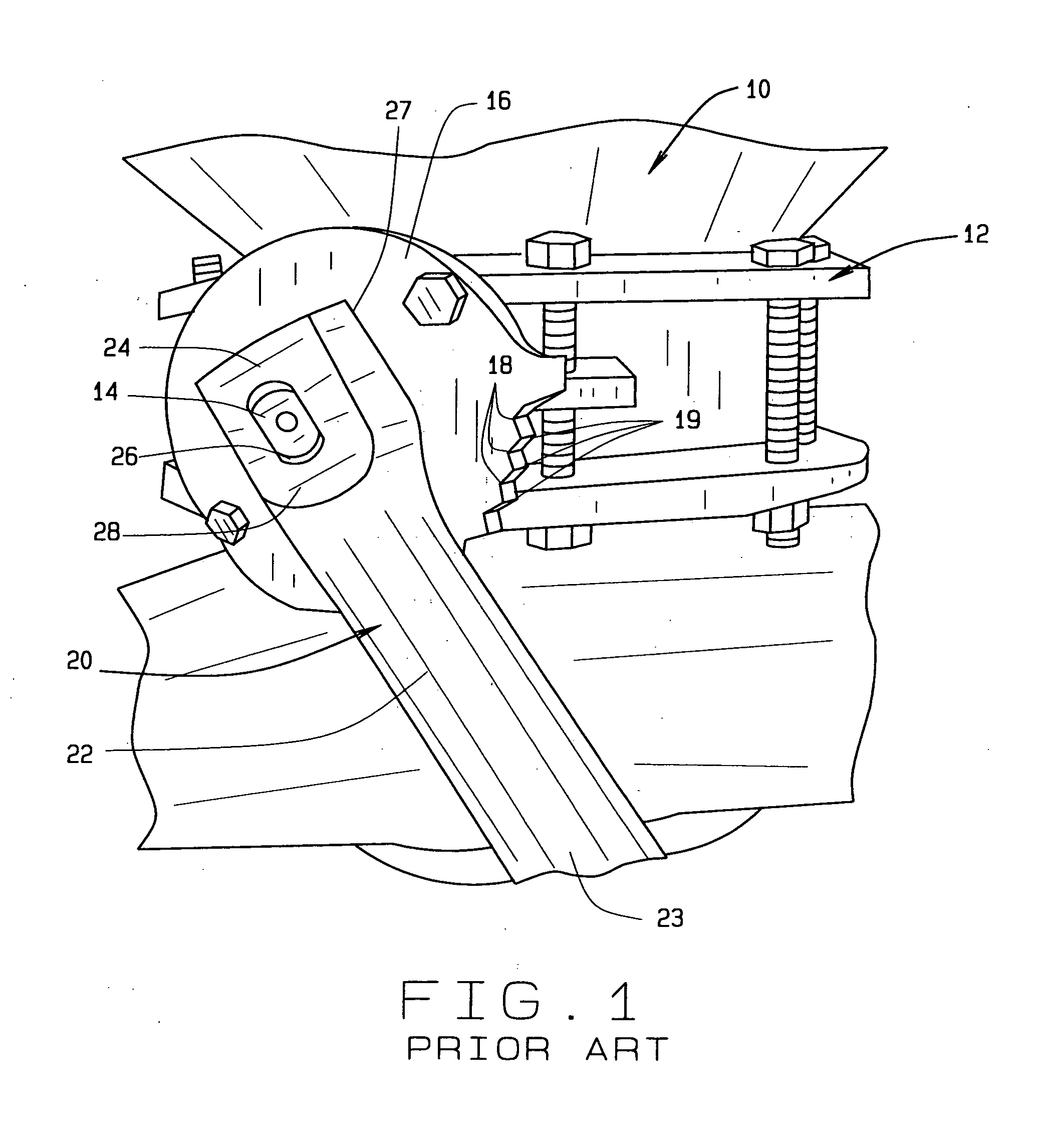
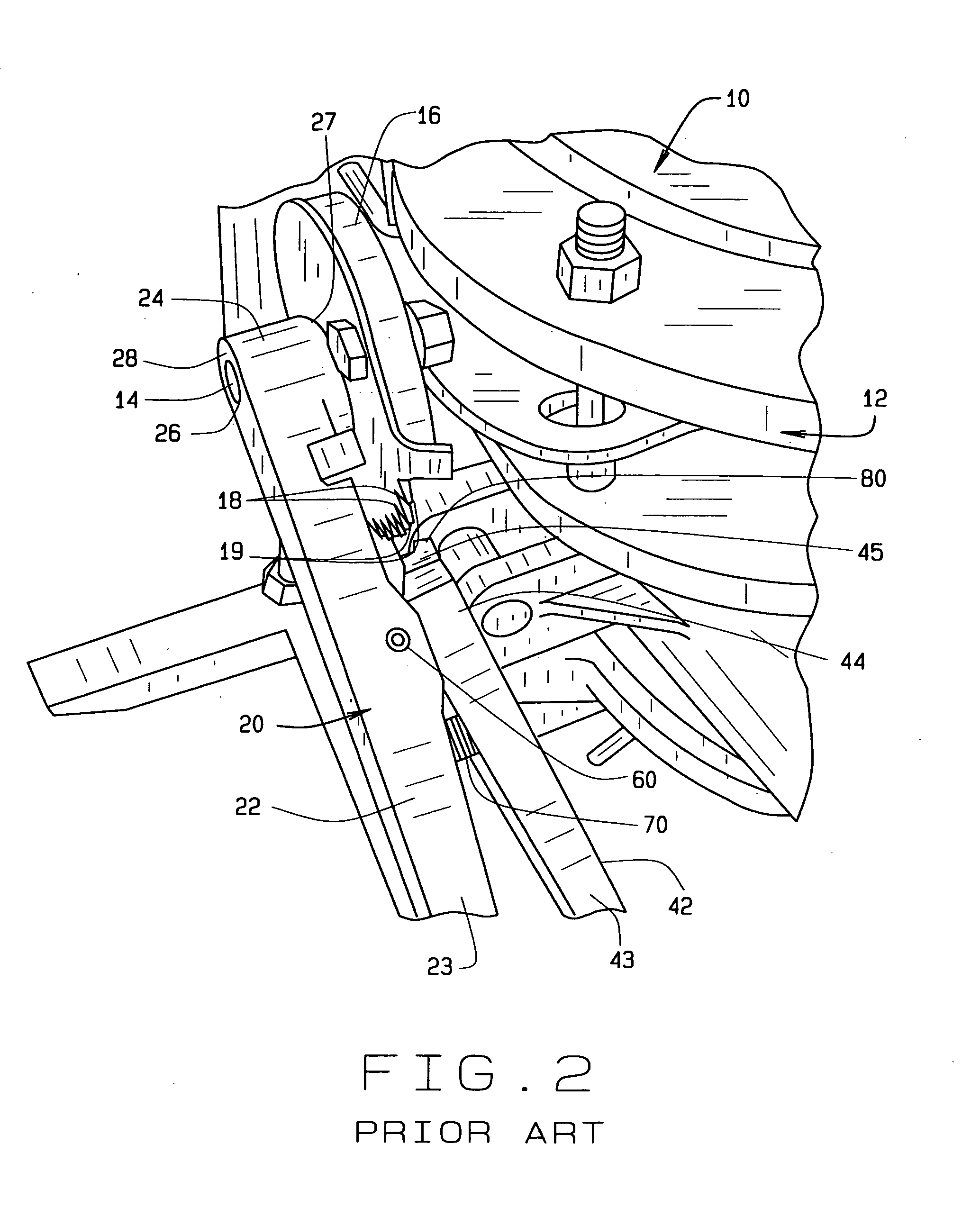
[0043]Referring now to the drawings, wherein like numbers generally refer to like items, FIGS. 1-3 all depict a bulk commodity hopper 10 having a discharge valve construction mounted near the base of the hopper 10 for controlling the discharge of material therefrom. The discharge valve construction 12 includes therewith a valve stem 14 projecting outwardly sidewardly and generally horizontally from near the base of the hopper 10 and lock lever plates 16 disposed generally perpendicular to valve stem 14 and interiorly to the outer end of valve stem 14. A plurality of lock lever position notches 18, with intervening teeth 19 therebetween, is shown formed along a portion of the outer periphery of lock lever plate 16.

[0044]All of such FIGS. 1-3 also depict a prior art valve handle 20 that includes a handle bar 22 having a proximate end portion 23 and a distal end portion 24 with a socket opening 26 extending therethrough from the inner side 27 to the outer side 28 of the handle bar 22. ...


PUM


Abstract

A valve handle for a bulk commodity hopper valve, the handle including an extended handle bar member, with a valve stem socket opening near its distal end, a shorter lock lever member positioned to extend the handle bar member, the members have various bends to provide clearance from interfering with the equipment to which the handle mounts, and a lock lever member having a lever tip that can enter into engagement, or release, with valve lock notches at the end of the handle bar member.

Description

CROSS REFERENCE TO RELATED APPLICATIONS[0001]This utility application claims priority to the provisional application having Ser. No. 61 / 517,041, filed Apr. 12, 2011, which claims priority to pending design application having Ser. No. 29 / 372,802, filed Jan. 13, 2011, commonly owned by the same inventor.FIELD OF THE INVENTION[0002]This invention is directed to a valve handle for operating a butterfly valve of the type associated with hopper tees at the bottoms of bulk commodity hoppers for use in unloading the contents of the bulk commodity hoppers.BACKGROUND OF THE INVENTION[0003]Hoppers and tank trailers have been commonly employed for many years to transport bulk commodities such as industrial and food products, including industrial products such as pelletized plastics and the like, and food products such as milled flours and the like. The hoppers often include multiple sections or compartments for receiving and holding the products, with each section or compartment having a genera...

Claims


Application Information

Patent Timeline
18 Oct 2012
Publication
US20120261602A1
IPC
F16K31/60
CPC
B60P1/56; F16K35/025; F16K31/602; Y10T137/5196
Inventors
SISK, DAVID E.