
System and Method for Background Calibration of Time Interleaved Analog to Digital Converters

a technology of interleaved analog and digital converters, applied in the field of interleaved analog to digital converters, can solve the problems of limiting i-adc performance, introducing a number of component errors in each adc channel, and i-adcs being known to give rise to new performance limiting errors, so as to reduce channel-to-channel mismatch errors

Active Publication Date: 2012-10-18
MAXIM INTEGRATED PROD INC
View PDF7 Cites 39 Cited by
  • Summary
  • Abstract
  • Description
  • Claims
  • Application Information

AI Technical Summary

Benefits of technology

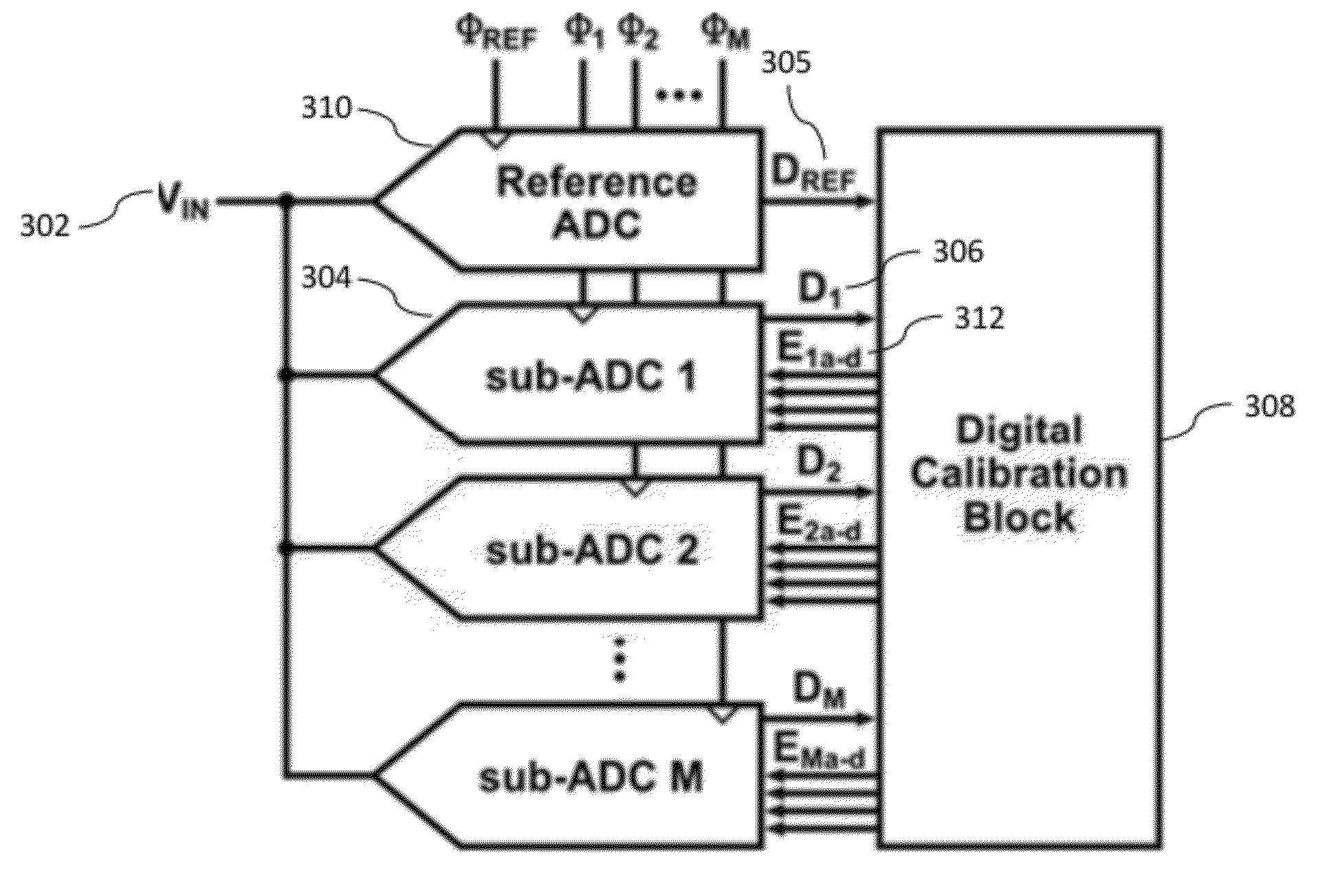
The invention provides a way to calibrate the channels of high-speed analog-to-digital converters (ADCs) to reduce errors caused by sources within the ADCs. This calibration involves comparing the output of a pre-calibrated reference ADC to the output of sub-ADCs and using the difference to correct specific errors. The invention also takes advantage of information from the input signal to define a function representing a known error and use it to estimate and correct for errors in the sub-ADCs. The reference ADC samples the analog input signal at a known timing relationship with the sub-ADCs to align with their sampling locations. The technical effect of the invention is to improve the accuracy and reliability of high-speed analog-to-digital conversion.

Problems solved by technology

In practice, each ADC channel introduces a number of component errors, such as phase shift errors in the clock signals.
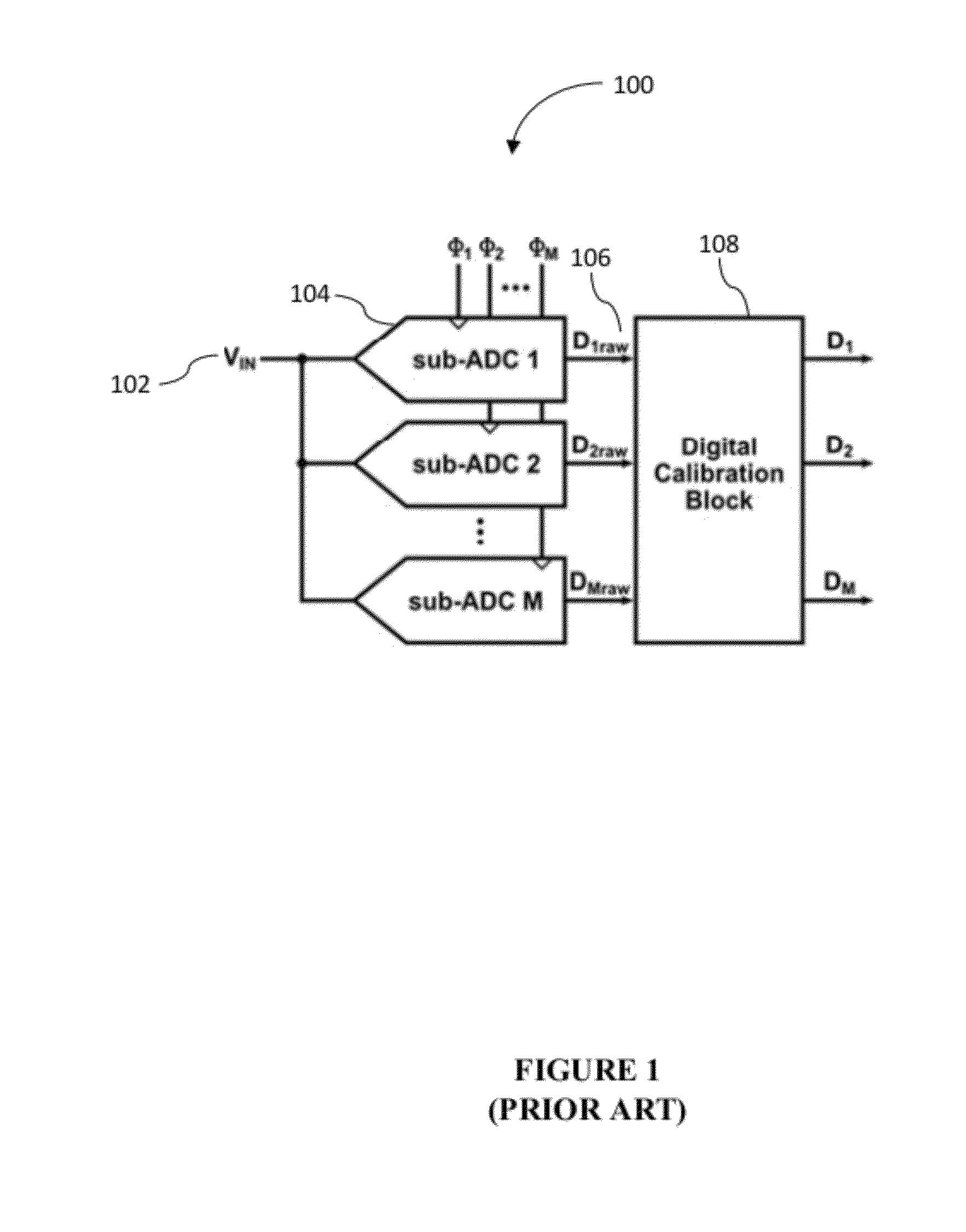
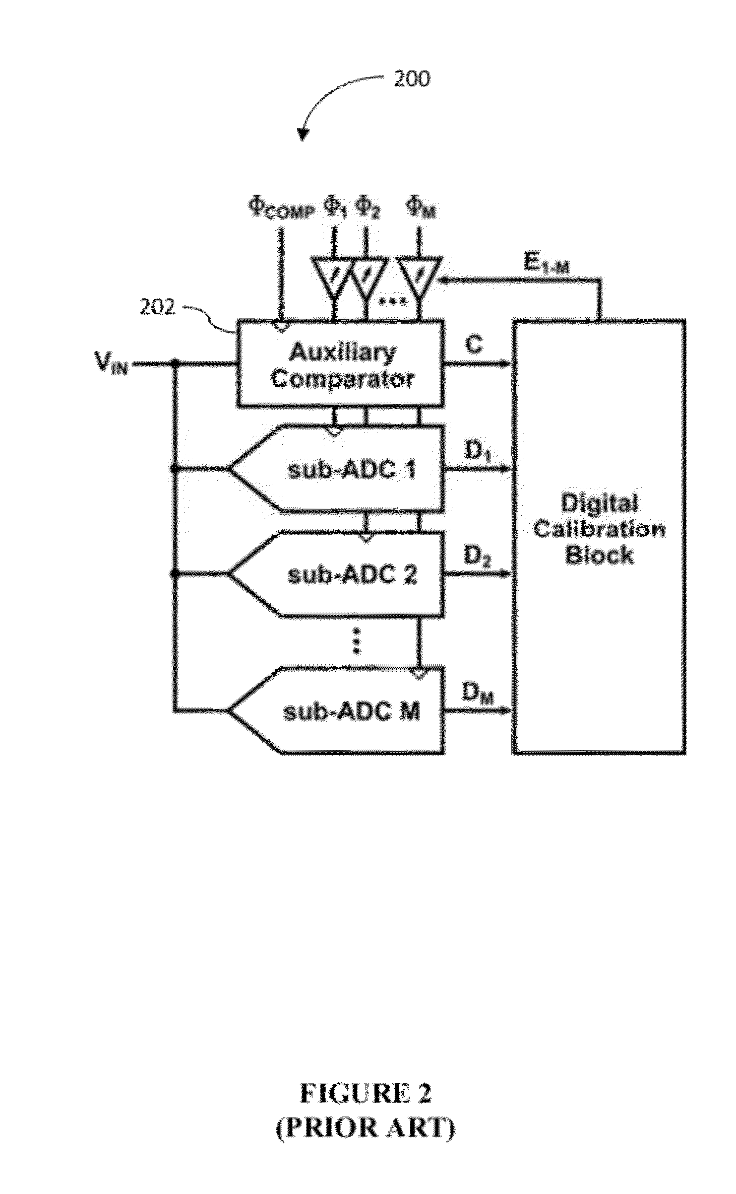
I-ADCs are known to give rise to new performance limiting errors that are caused by transfer path mismatch (e.g. propagation delay), gain, and offset mismatch between the multiple ADC channels.
The combined channel mismatch error may modulate nonlinearly with the unknown analog input signal and create signal-dependent error terms that further limit I-ADC performance.
Moreover, drifts temperature, power supply voltage, and other environmental conditions may change the mismatch error over time, which requires additional mismatch calibration.
Although many solutions have been proposed to minimize, compensate, or calibrate the various sources of mismatch, mismatch error remains a bottleneck for high-precision, high-speed sampling of high-frequency input signals.

Method used


Image

  • System and Method for Background Calibration of Time Interleaved Analog to Digital Converters
  • System and Method for Background Calibration of Time Interleaved Analog to Digital Converters
  • System and Method for Background Calibration of Time Interleaved Analog to Digital Converters

Examples


Embodiment Construction

[0027]In the following description, for the purpose of explanation, specific details are set forth in order to provide an understanding of the invention. It will be apparent, however, to one skilled in the art that the invention can be practiced without these details. One skilled in the art will recognize that embodiments of the present invention, described below, may be performed in a variety of ways and using a variety of means. Those skilled in the art will also recognize additional modifications, applications, and embodiments are within the scope thereof, as are additional fields in which the invention may provide utility. Accordingly, the embodiments described below are illustrative of specific embodiments of the invention and are meant to avoid obscuring the invention.

[0028]Reference in the specification to “one embodiment” or “an embodiment” means that a particular feature, structure, characteristic, or function described in connection with the embodiment is included in at le...


PUM


Abstract

Various embodiments allow for background calibration of channel-to-channel mismatch errors.In certain embodiments calibration is accomplished by comparing the output of I-ADCs against the output of a reference ADC and correlating the difference to a known function to obtain a correction signal that can be used to correct channel-to-channel mismatch errors.

Description

CROSS REFERENCE TO RELATED PATENT APPLICATIONS[0001]This application claims priority to U.S. Provisional Application Ser. No. 61 / 474,401, entitled “SYSTEM AND METHOD FOR BACKGROUND CALIBRATION OF TIME-INTERLEAVED ANALOG-TO-DIGITAL CONVERTERS,” filed Apr. 12, 2011, which application is incorporated herein by reference in its entirety.BACKGROUND[0002]A. Technical Field[0003]The present invention relates to interleaved analog-to-digital converters, and more particularly, to systems, devices, and methods of calibrating channel-to-channel mismatch error caused by one or more sources in interleaved analog-to-digital converters.[0004]B. Background of the Invention[0005]Time interleaved analog-to-digital converter (I-ADC) technology allows for power-efficient, high-speed sampling and digitization of analog input signals. In single ADC channel architectures, three competing parameters 1) precision, 2) speed, and 3) power are typically traded against each other. An I-ADC architecture allows t...

Claims


Application Information

Patent Timeline
Patent Type & Authority Applications(United States)
IPC IPC(8): H03M1/10
CPCH03M1/1215H03M1/1057
Inventor STRAAYER, MATTHEW ALLEN ZORNIGLEE, HAE-SEUNG
Owner MAXIM INTEGRATED PROD INC
Learn More