Sealing device for turbocharger
a sealing device and turbocharger technology, applied in the direction of machines/engines, stators, liquid fuel engines, etc., can solve problems such as inability to meet the needs of customers, and achieve the effect of improving sealability and simple structur
- Summary
- Abstract
- Description
- Claims
- Application Information
AI Technical Summary
Benefits of technology
Problems solved by technology
Method used
Image
Examples
first embodiment
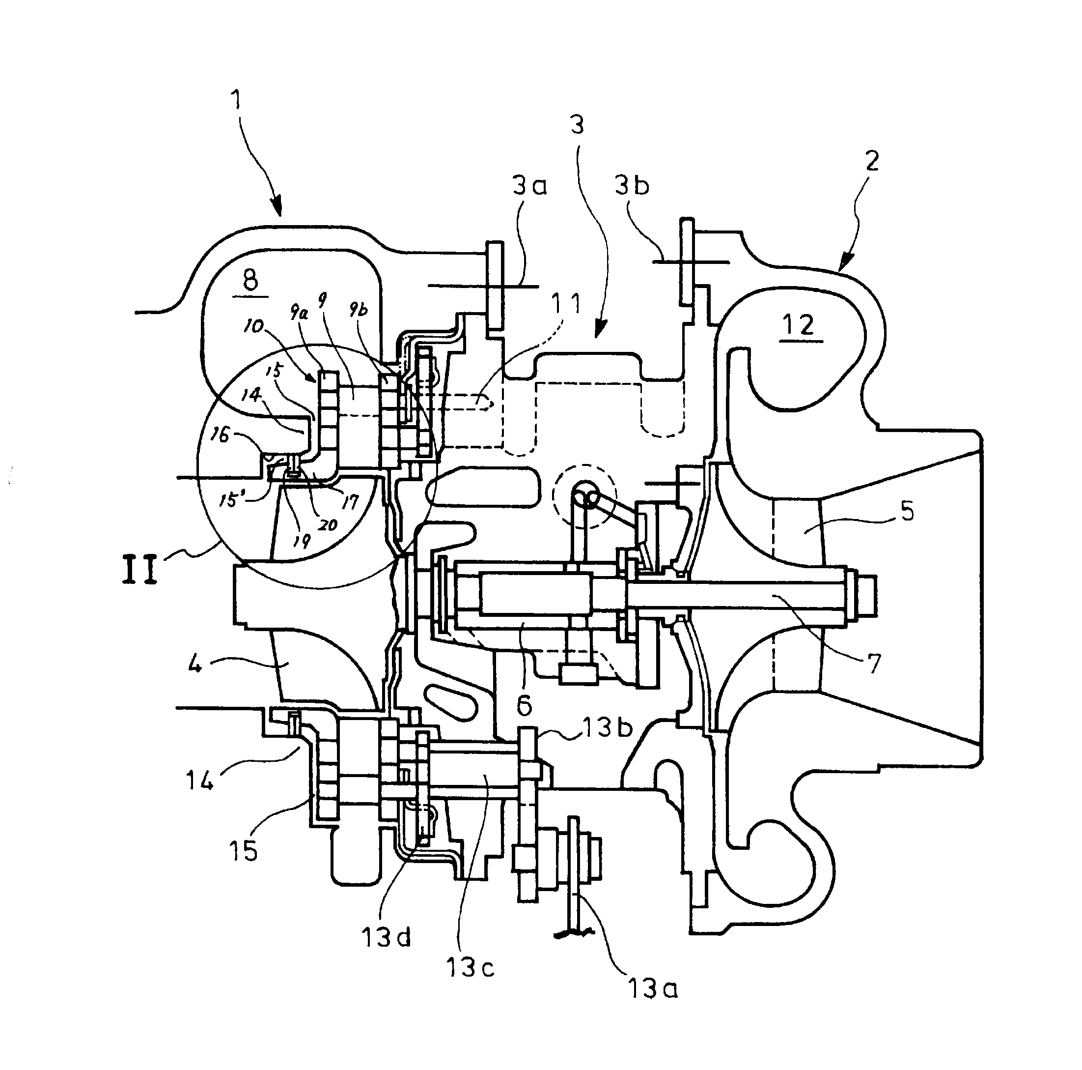
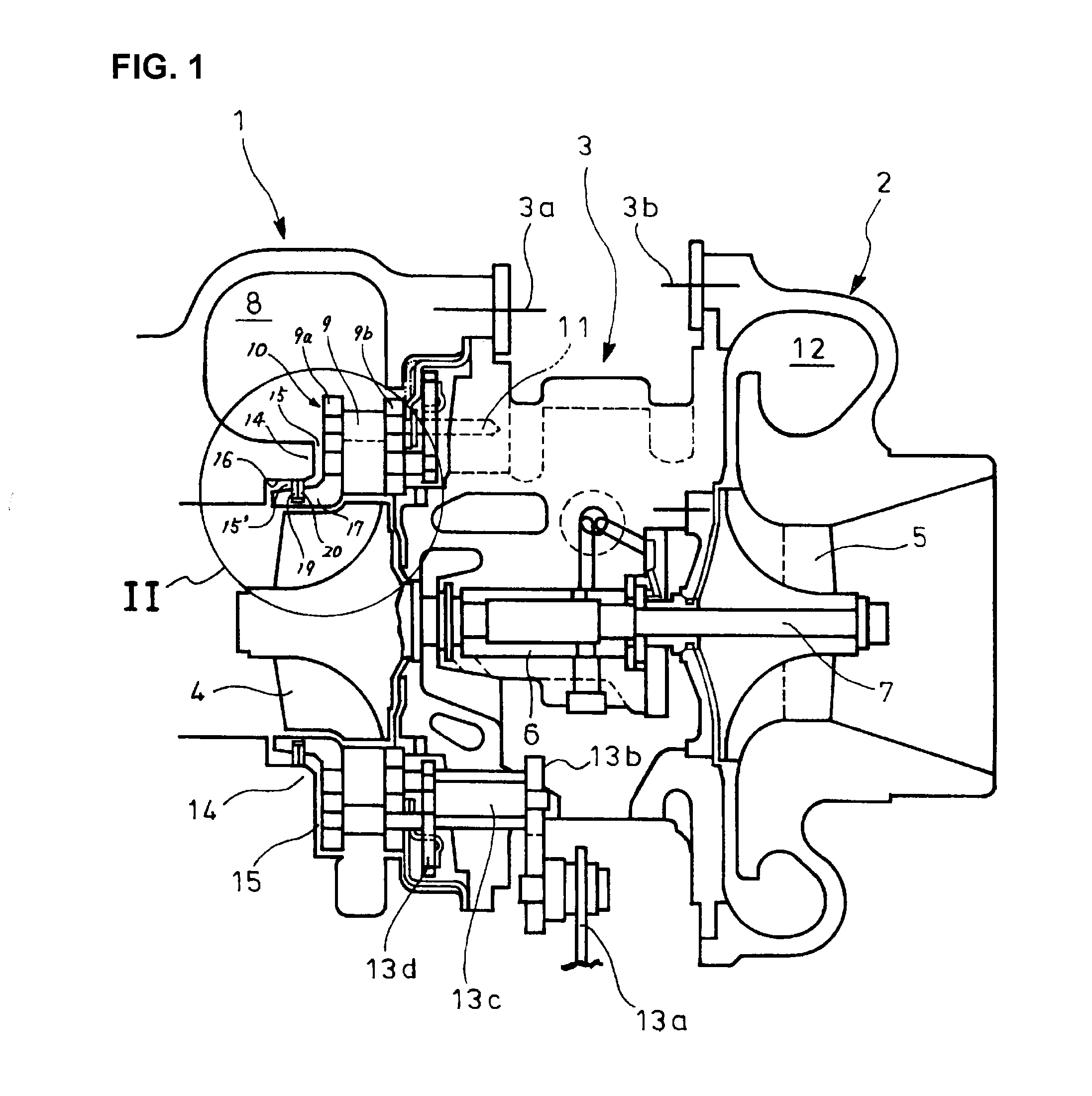
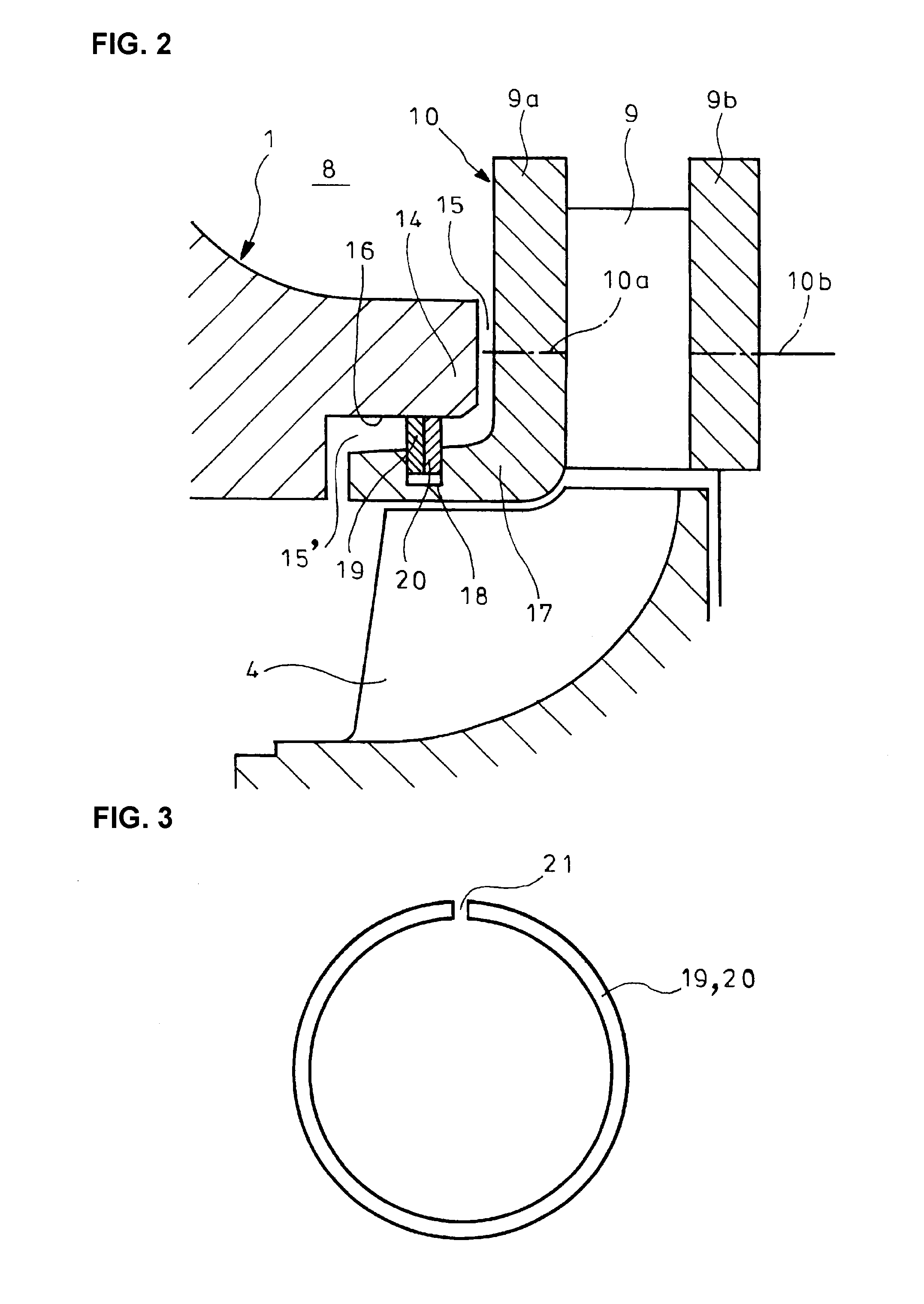
[0042]FIGS. 4 to 7 show a sealing device for a turbocharger of the invention in which parts similar to those in FIGS. 1 and 2 are represented by the same reference numerals. The sealing device comprises a seal body 24 formed annularly as shown in FIGS. 5 and 6 to have an fitted / fixed portion 25 airtightly fitted and fixed to a shoulder 22 in a turbine housing 1 formed facing a scroll passage 8 and have a clearance facing portion 27 facing an outer periphery of a turbine-housing-side exhaust introducing wall 9a of an exhaust nozzle 10 with a clearance S, the clearance facing portion 27 being caused to be pressed against the exhaust introducing wall 9a due to a difference in fluid pressure between the clearance S and the scroll passage 8. The fitted / fixed portion 25 of the seal body 24 is formed with slipout preventive means 29 for prevention of the fitted / fixed portion 25 from slipping out of the shoulder 22.
[0043]In the first embodiment, the shoulder 22 comprises, as shown in FIG. 4...
second embodiment
[0058]An operation of the second embodiment will be described.
[0059]The fitted / fixed portion 25 of the seal body 24 is preliminarily fitted and fixed by press fitting the same to the shoulder 22 in the turbine housing 1 formed facing the scroll passage 8 such that the inner cylindrical portion 25b is displaced beyond the protrusion 30 acting as the slipout preventive means 29. Since the inner cylindrical portion 25b of the seal body 24 is preliminarily formed to have a bore diameter airtightly fittable to the cylindrical wall 22b of the shoulder 22, the inner cylindrical portion 25b is airtightly fitted and fixed to the cylindrical wall 22b after the inner cylindrical portion 25b is displaced beyond the protrusion 30 acting as the slipout preventive means 29.
[0060]Moreover, the open end of the inner cylindrical portion 25b of the fitted / fixed portion 25 is engaged with the protrusion 30 acting as the slipout preventive means 29 as shown in FIGS. 8 and 9, the fitted / fixed portion 25 ...
third embodiment
[0067]An operation of the third embodiment will be described.
[0068]The fitted / fixed portion 25 of the seal body 24 is preliminarily fitted and fixed by press fitting the same into the shoulder 22 in the turbine housing 1 formed facing the scroll passage 8 such that the inner peripheral end of the inner annular portion 25a is fitted into the groove 31 acting as the slipout preventive means 29. Since the inner peripheral end of the inner annular portion 25a of the seal body 24 is preliminarily formed to have the bore diameter airtightly fittable into the recessed groove 31 as the slipout preventive means 29 on the cylindrical wall 22b of the shoulder 22, the inner annular portion 25a is airtightly fixed to the cylindrical wall 22b while closely contacting the annular wall 22a.
[0069]Moreover, the inner peripheral end of the inner annular portion 25a of the fitted / fixed portion 25 is fitted into the recessed groove 31 acting as the slipout preventive means 29 as shown in FIG. 11, so th...
PUM
 Abstract
Description
Claims
Application Information
 - R&D
- Intellectual Property
- Life Sciences
- Materials
- Tech Scout
- Unparalleled Data Quality
- Higher Quality Content
- 60% Fewer Hallucinations
Browse by: Latest US Patents, China's latest patents, Technical Efficacy Thesaurus, Application Domain, Technology Topic, Popular Technical Reports.
© 2025 PatSnap. All rights reserved.Legal|Privacy policy|Modern Slavery Act Transparency Statement|Sitemap|About US| Contact US: help@patsnap.com


