Discrete Attachment Point Apparatus and System for Photovoltaic Arrays

a technology of photovoltaic arrays and attachment points, which is applied in the direction of heat collector mounting/support, lighting and heating apparatus, rod connections, etc., can solve the problems of -20 feet long, difficult to warehouse, ship, move onto a roof or other support surface,

Active Publication Date: 2012-10-25
TESLA INC
View PDF37 Cites 42 Cited by
  • Summary
  • Abstract
  • Description
  • Claims
  • Application Information

AI Technical Summary

Problems solved by technology

In the case of tile roofs, this may be due to the difficulty of installing an attachment device at anywhere other than a specific place relative to the tile.
Such conventional systems suffer from a number of drawbacks.
The long rails utilized, which can be often 10-20 feet long, may be difficult to warehouse, ship, and move onto a roof, or other support surface.
These rails may also limit mounting options on complicated roofs which may have numerous smaller roof surfaces and / or numerous obstructions (such as vent pipes, chimneys, and so on) since rails may need to be cut on site, potentially wasting time and materials.
Since rafters typically run in the direction from ridge to gutter, conventional long rail systems may be less cost-effective if the PV modules are oriented in “landscape” as opposed to “portrait” manner, since rails parallel to the rafters may require more total rail length or be prohibited, as by the PV module manufacturer or local building codes.
The mounting technology used to connect PV modules to these described long rails may also be cumbersome and time-consuming due to large numbers of small parts, including fasteners.
The attachment devices utilized may also be expensive and time-consuming to install.
Such conventional systems may further suffer from a lack of adaptability to uneven roof surfaces as well as time-consuming and unreliable grounding hardware.
There may also be very little integration with other required equipment in the overall PV system, such as electrical junction and combiner boxes, wire management devices, and other equipment.
This constraint may limit the ability of a system designer to optimize the structural support system so that the level of support provided is substantially matched to the level of support required, based on various site conditions such as wind, snow, roof structure, and so on.
Lack of structural optimization could waste a significant quantity of materials relative to a more optimized approach.
Other limitations of the related art will become apparent to those of skill in the art upon a reading of the specification and a study of the figures.

Method used


Image

  • Discrete Attachment Point Apparatus and System for Photovoltaic Arrays
  • Discrete Attachment Point Apparatus and System for Photovoltaic Arrays
  • Discrete Attachment Point Apparatus and System for Photovoltaic Arrays

Examples


Embodiment Construction

[0064]Terms. With reference to the figure and description herein:

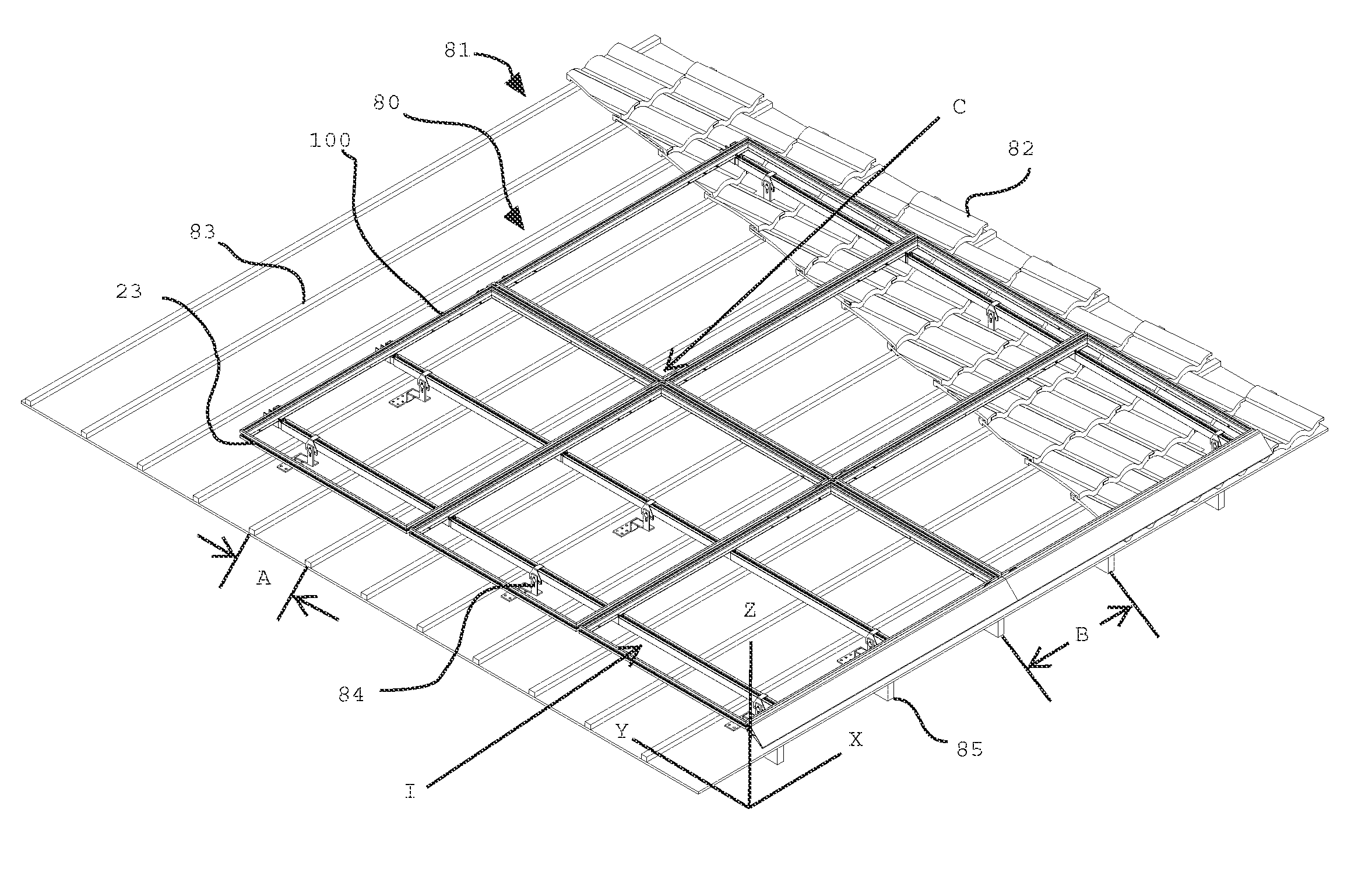
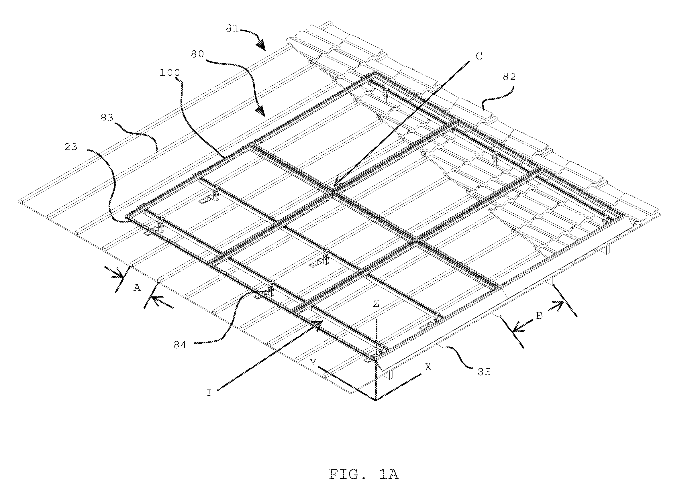
[0065]Adjacent refers to being positioned next to or adjoining or neighboring, or having a common vertex or common side. Thus, adjacent PV panels would include PV panels that have one side close to (from a few inches apart to abutting) and facing one side of another PV panel, such as shown in FIGS. 1a and 20. Sometimes, but not always, the corners of adjacent panels align; so four adjacent panels would have one corner each that nearly or actually touch the other three corners, such as exemplified at Point C in FIGS. 1a and 20, and its descriptions.

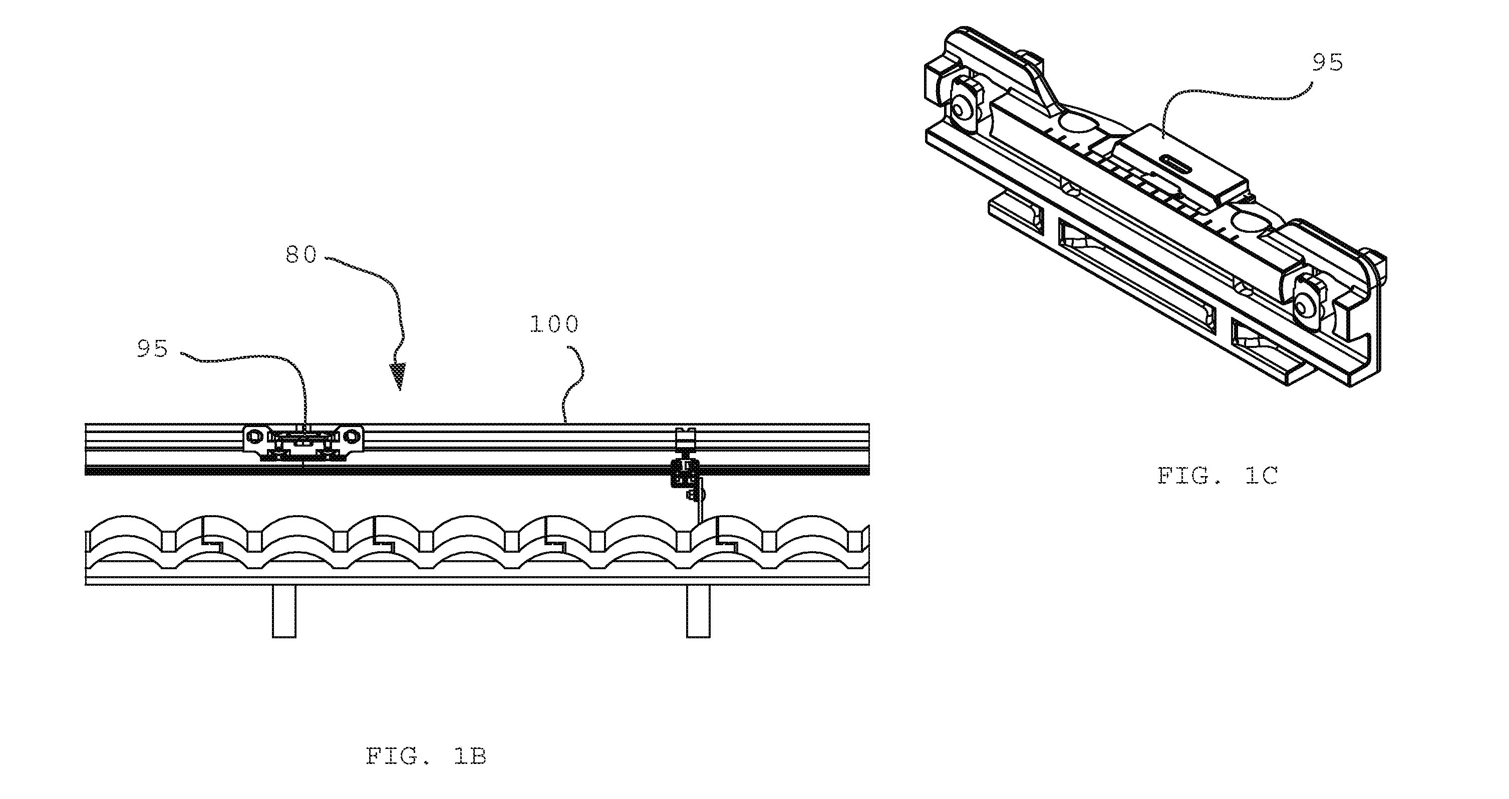
[0066]Attach or attachment refers to one or more items, mechanisms, objects, things, structures or the like which are joined, fastened, secured, affixed or connected to another item, or the like in a permanent, removable, secured or non-permanent manner. For example, a tile hook may be attached to a support structure, such as a roof, as exemplified at tile hook 84 in FIG. 1a,...


PUM


Abstract

An attachment point apparatus and system for photovoltaic arrays is disclosed. One embodiment provides a rail system for receiving a PV module, including a first rail, a second rail, a substantially rectilinear double male connector adapted for coupling an end of the first rail to an end of the second rail, and a connector adapted to attach a PV module to the first rail. Another embodiment provides a PV module including a PV laminate, a frame integral with and supporting the PV laminate, and a spanner bar adapted to solely span a width of the PV module, orthogonally connect at various locations along the frame, and attach to a support structure. A further embodiment provides a coupling device for a PV module comprising a first coupling portion adapted to rotatably engage a PV module, and a second coupling portion adapted to rotatably engage a rail.

Description

CROSS REFERENCES[0001]The present application is a continuation of U.S. application Ser. No. 13 / 325,054, filed Dec. 13, 2011, and claims the benefit of the filing date of U.S. Provisional Patent Application Ser. No. 61 / 445,044, filed Feb. 22, 2011. The foregoing applications are incorporated by reference in their entirety as if fully set forth herein.BACKGROUND[0002]Many photovoltaic (PV) arrays are mounted on structures that require discrete attachment points. For example, tile and slate roofs and various types of ground mounted structures may include a support structure for a PV array that requires attachment of the PV array to the structure at discrete locations in one of or both the x and y axes of a PV array mounting plane. In the case of tile roofs, this may be due to the difficulty of installing an attachment device at anywhere other than a specific place relative to the tile. For example, some tile products may only allow an attachment device to be installed within a small r...

Claims


Application Information

Patent Timeline
Patent Type & Authority Applications(United States)
IPC IPC(8): H01L31/048F16D1/12F16B5/00
CPCY02B10/12F24J2/5205F24J2/5247F24J2/5254F24J2/5258F24J2/526Y10T403/32975F24J2002/5215F24J2002/5226Y02E10/47H02S20/23Y10T403/38F24J2/5264F24S25/33F24S25/613F24S25/632F24S25/636F24S25/65F24S25/70F24S2025/801F24S2025/807Y02B10/10Y02B10/20Y02E10/50
Inventor WEST, JOHN RAYMONDYOUMANS, DAVIDATCHLEY, BRIAN
Owner TESLA INC
Why Eureka
Try Eureka