Maximum power point tracking (MPPT) method of currentless sensor

A technology of maximum power point and sensor, which is used in instruments, photovoltaic power generation, and adjustment of electrical variables to achieve accurate maximum power point tracking, wide application prospects, and improved reliability.

Inactive Publication Date: 2011-05-04
盈威力新能源科技(上海)有限公司
View PDF4 Cites 16 Cited by
  • Summary
  • Abstract
  • Description
  • Claims
  • Application Information

AI Technical Summary

Problems solved by technology

However, these methods ignore an important information, that is, during the dynamic transition process with the MPPT cycle as the time unit, the voltage ripple on the capacitor contains the information of the output power of the photovoltaic array.

Method used


Image

  • Maximum power point tracking (MPPT) method of currentless sensor
  • Maximum power point tracking (MPPT) method of currentless sensor
  • Maximum power point tracking (MPPT) method of currentless sensor

Examples


Embodiment Construction

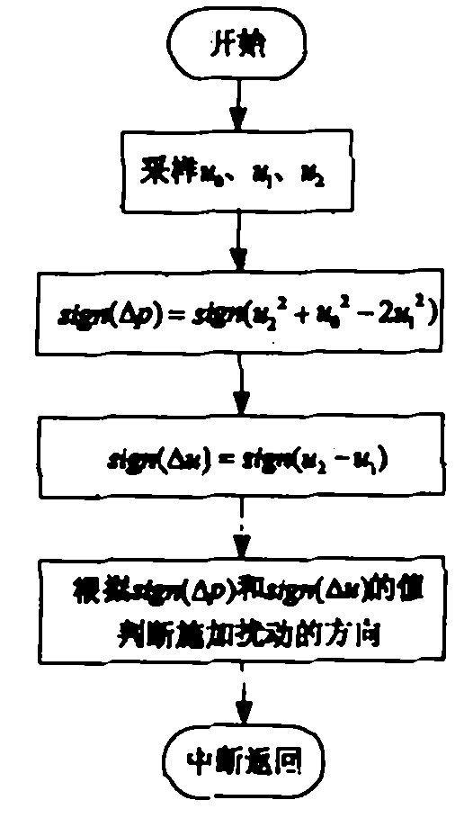
[0027] The flow chart of the maximum power point tracking method without current sensor according to the present invention is as follows figure 1 As stated, detect u 0 , u 1 , u 2 respectively corresponding to t 0 , t 0 + T, t 0 The capacitor voltage value at +2T time. Let sign(Δp)=u 2 2 + u 0 2 -2u 1 2 , sign(Δu)=u 2 -u 1 , according to the value of sign(Δp) and sign(Δu) to judge the direction of the disturbance.

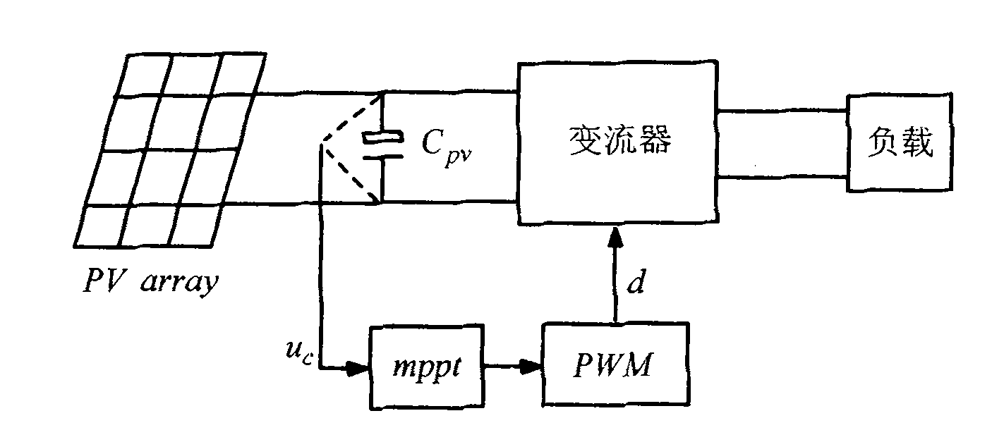
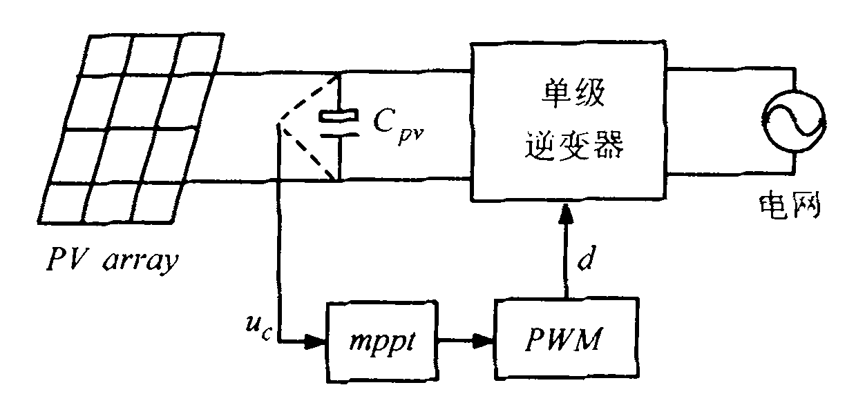
[0028] figure 2 Shown is the system control structure diagram of the maximum power point tracking method without current sensor of the present invention. The theoretical basis is that the capacitance C between the solar cell and the converter during the dynamic transition pv Upper voltage u c The ripple contains information about the output power of the photovoltaic array. By calculating the change value of the capacitor voltage after two consecutive MPPT cycles, the change direction of the output power of the photovoltaic array can be obtained, ...


PUM


Abstract

The invention discloses a maximum power point tracking (MPPT) method of a currentless sensor, belonging to the technical field of new energy. In the method, because the ripple of voltages on a capacitor between a photovoltaic array and a convertor during the dynamic transition process comprises the information of the output power of the photovoltaic array, the variation direction of the output power of the photovoltaic array can be obtained by calculating the variation value of the voltages of the capacitor after two continuous MPPT periods so as to track the maximum power point of the photovoltaic array. Compared with the common MPPT method, the method provided by the invention has the advantages that the variation direction of the output power of the photovoltaic array can be judged without a current sensor, the maximum power point can be accurately tracked, the system cost is lowered, and the system reliability is improved, thereby having certain practical value. Thus, the method provided by the invention has wide application prospect in the aspect of new energy power generation, especially in solar power generation.

Description

technical field [0001] The invention relates to a maximum power point tracking method, in particular to a maximum power point tracking method without a current sensor, which belongs to the technical field of new energy, especially the field of photovoltaic power generation. technical background [0002] Photovoltaic array is the core and key component of solar photovoltaic power generation system. According to the I-V characteristics of solar cells, solar cells have maximum power points under different sunlight intensities and cell temperatures. Therefore, in order to make full use of the output energy of solar cells and maximize the effectiveness of solar cells, the photovoltaic array must always work At the maximum power point, the technology of maximum power point tracking needs to be adopted. [0003] Several MPPT methods commonly used at present mainly include: constant voltage method, perturbation and observation method (P&O, Perturbation and Observation), also known ...

Claims


Application Information

Patent Timeline
Patent Type & Authority Applications(China)
IPC IPC(8): G05F1/67
CPCY02E10/56
Inventor 古俊银
Owner 盈威力新能源科技(上海)有限公司
Why Eureka
Try Eureka