Device and method for tracking maximum power point in partial shadow of photovoltaic power generation system

A photovoltaic power generation system and maximum power point technology, which is applied in photovoltaic power generation, control/regulation systems, and electrical variable adjustment, etc., can solve the problem of the maximum power point falling into local optimum, etc. Effect

Active Publication Date: 2017-06-16
HOHAI UNIV
View PDF6 Cites 0 Cited by
  • Summary
  • Abstract
  • Description
  • Claims
  • Application Information

AI Technical Summary

Problems solved by technology

[0005] The purpose of the present invention is to overcome the deficiencies in the prior art, provide a maximum power point tracking device and its tracking method under partial shadow of a photovoltaic power generation system, and solve the problem that traditional maximum power point tracking in the prior art tends to fall into local optimum technical problem

Method used


Image

  • Device and method for tracking maximum power point in partial shadow of photovoltaic power generation system
  • Device and method for tracking maximum power point in partial shadow of photovoltaic power generation system
  • Device and method for tracking maximum power point in partial shadow of photovoltaic power generation system

Examples


Embodiment 1

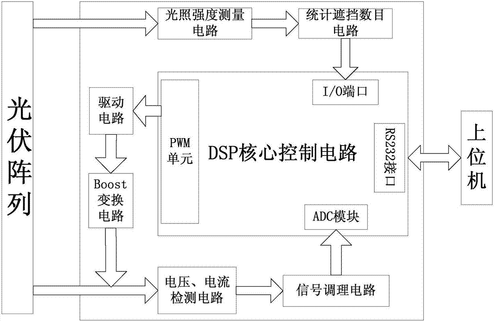
[0062] The specific working process of the present invention is described below with specific embodiments. At the initial moment, the light intensity is uniform, and the shading number circuit does not detect the shading of the photovoltaic array. The voltage and current detection circuit collects the voltage and current value of the photovoltaic array, and passes through the signal After the conditioning circuit is processed, it is sent to the ADC module of the DSP. At this time, the DSP microcontroller outputs the PWM wave with the corresponding duty cycle through the conductance incremental method to drive the boost conversion circuit. On the other hand, the voltage and current values ​​are transmitted to the Host computer; the maximum power point of the photovoltaic array is finally tracked at point A, and the corresponding voltage value is V A , the power value is P A . After a period of time, when the shading counting circuit detects shading of the photovoltaic array, i...

Embodiment 2

[0064] In order to verify the actual effectiveness of the method of the present invention, the present invention actually simulates the situation of light blocking when two photovoltaic units are connected in series. Figure 6 (a), (b) is the light intensity of 1 / 1 (kW / m 2 ) and 1 / 0.8(kW / m 2 ) I-V, P-V output characteristic curves. Based on the above experimental platform, when t=80s, set the light intensity in the photovoltaic array I-V simulator by 1 / 1(kW / m 2 ) becomes 1 / 0.8(kW / m 2 ); when t Figure 7 and Figure 8 As shown, the maximum power point and the maximum power point searched by the present invention before and after occlusion appear Figure 6 The voltage and current values ​​at the actual global maximum power point in (a) and (b) are compared, and the results show that they are equal within a reasonable error range.


PUM


Abstract

The invention discloses a device and a method for tracing a maximum power point under the partial shade of a photovoltaic power generation system. The method comprises the following concrete steps that when a photovoltaic array is not shielded, the maximum power point is quickly searched by utilizing a conductance increment method; when the photovoltaic array is shielded, firstly building a load line function, utilizing the load line function to enable a work point to jump out of a partial optimum section, then combining the conductance increment method to quickly position the maximum power point in each partial section, so that the tracing of the global maximum power point is realized. The device is clear in structure, definite in function, convenient to implement, and in particular applicable to sudden change situations of illumination intensity, so that the maximum power point tracing efficiency is improved, and the energy loss is reduced.

Description

technical field [0001] The invention relates to a maximum power point tracking device under partial shadow of a photovoltaic power generation system, and also relates to a maximum power point tracking method under partial shadow of a photovoltaic power generation system, which belongs to the technical field of maximum power point tracking in photovoltaic power generation systems. Background technique [0002] In the photovoltaic power generation system, the maximum power point tracking (Maximum Power Point Tracking, MPPT) problem is one of the most concerned issues for researchers, that is, to keep the system working at the peak point of the power curve and convert solar energy into electrical energy with maximum efficiency. [0003] Under the condition of constant sunlight intensity and operating temperature, the PV module has a unique maximum power point in its P-V characteristic curve. However, under partial shading conditions, mismatched cells not only do not contribute t...

Claims


Application Information

Patent Timeline
Patent Type & Authority Patents(China)
IPC IPC(8): G05F1/67
CPCG05F1/67Y02B10/10Y02E10/56
Inventor 王冰胡庆燚
Owner HOHAI UNIV
Why Eureka
Try Eureka