
A method and system for maximum power point tracking

A technology of maximum power point and tracking system, applied in photovoltaic power generation, AC network circuits, electrical components, etc., can solve problems such as complexity and high cost of sensor signal processing circuits, and achieve the effect of improving reliability and reducing costs

Active Publication Date: 2017-02-01
NR ELECTRIC CO LTD +2
View PDF4 Cites 0 Cited by
  • Summary
  • Abstract
  • Description
  • Claims
  • Application Information

AI Technical Summary

Problems solved by technology

Numerous sensors and their signal processing circuits bring high cost and complexity

Method used


Image

  • A method and system for maximum power point tracking
  • A method and system for maximum power point tracking
  • A method and system for maximum power point tracking

Examples


Embodiment Construction

[0053] The technical solutions of the present invention will be further elaborated below in conjunction with the accompanying drawings and specific embodiments.

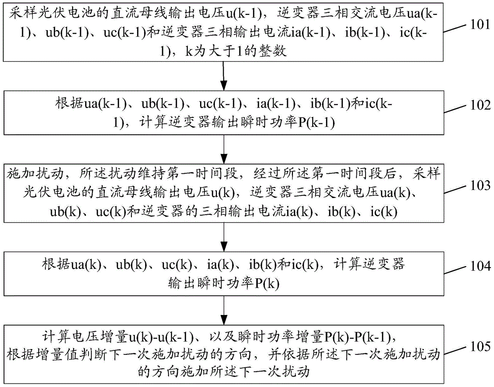
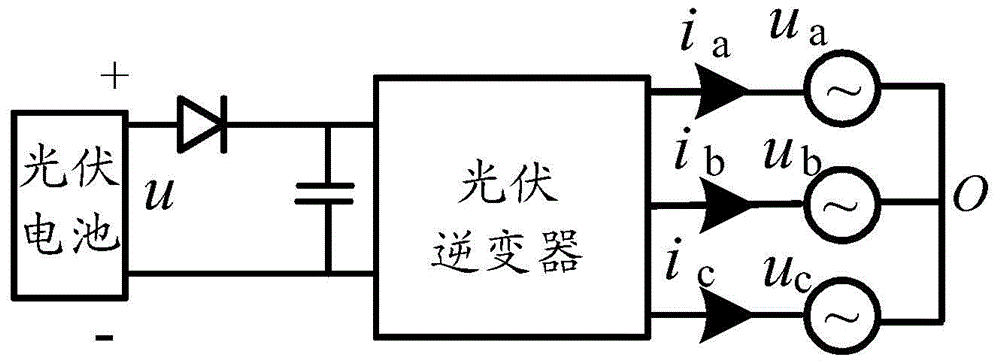
[0054] An embodiment of the present invention provides a maximum power point tracking method, which is suitable for figure 2 In the photovoltaic power generation system shown, such as figure 2 As shown, the photovoltaic power generation system includes photovoltaic cells and photovoltaic inverters; the maximum power point tracking method is as follows figure 1 As shown, it mainly includes the following steps:

[0055] Step 101, sampling the DC bus output voltage u(k-1) of the photovoltaic cell, the three-phase AC voltage ua(k-1), ub(k-1), uc(k-1) of the inverter and the three-phase AC voltage of the inverter Phase output current ia(k-1), ib(k-1), ic(k-1), k is an integer greater than 1.

[0056] The DC bus output voltage of the photovoltaic cell is also the DC input voltage of the photovoltaic inverter, and the ...


PUM


Abstract

The invention discloses a tracking method for the maximum power point. The tracking method comprises the following steps: sampling a direct current bus output voltage u(k-1) of a photovoltaic cell, three-phase ac voltages ua(k-1), ub(k-1) and uc(k-1) of an inverter and three-phase output currents ia(k-1), ib(k-1) and ic(k-1) of the inverter, wherein k is an integer greater than 1; calculating an output instantaneous power P(k-1) of the inverter according to the ua(k-1), ub(k-1), uc(k-1), ia(k-1), ib(k-1) and ic(k-1); applying disturbance which is maintained in a first time quantum, and after the first time quantum, sampling the direct current bus output voltage u(k) of the photovoltaic cell, the three-phase ac voltages ua(k), ub(k) and uc(k) of the inverter and the three-phase output currents ia(k), ib(k) and ic(k) of the inverter; calculating the output instantaneous power P(k) of the inverter according to the ua(k), ub(k), uc(k), ia(k), ib(k) and ic(k); calculating voltage increment u(k)-u(k-1) and instantaneous power increment P(k)-P(k-1), judging the direction of applying disturbance next time according to the increment and applying disturbance next time according to the direction of applying disturbance next time. According to the invention, the maximum power point of a currentless sensor which is low in cost, high in reliability and suitable for photovoltaic power generation is tracked.

Description

technical field [0001] The invention relates to the technical field of photovoltaic power generation, in particular to a maximum power point tracking method and system. Background technique [0002] In the photovoltaic power generation system, the photovoltaic cell is the most basic link. To improve the efficiency of the entire system, the conversion efficiency of the photovoltaic cell must be improved to maximize the output power. However, the current (I)-voltage (V) characteristics of photovoltaic cells are nonlinear, and they change with changes in the external environment (temperature, light intensity). When the operating voltage of photovoltaic cells changes, their output power will also change; in order To always obtain maximum output power, maximum power point tracking (MPPT) is required. [0003] At present, the voltage source inverter is widely used. To realize the maximum power tracking control method, it is necessary to detect the grid voltage, input current, DC ...

Claims


Application Information

Patent Timeline
Patent Type & Authority Patents(China)
IPC IPC(8): H02J3/38
CPCH02J3/385Y02E10/56
Inventor 米高祥郭勇刘为群方太勋李旭
Owner NR ELECTRIC CO LTD
Learn More