
Energy harvesting device including MEMS composite transducer

a composite transducer and energy harvesting technology, applied in the direction of generators/motors, loudspeakers, machines/engines, etc., can solve the problems of inability to provide spatial compactness, reliability, and inability to operate independently of mems transducers. to achieve the effect of achieving the range of performance desired, and achieving the effect of reducing the cost of operation

Inactive Publication Date: 2012-10-25
EASTMAN KODAK CO
View PDF7 Cites 251 Cited by
  • Summary
  • Abstract
  • Description
  • Claims
  • Application Information

AI Technical Summary

Problems solved by technology

Based on material properties and geometries commonly used for MEMS transducers the amount of deflection can be limited, as can the frequency range, so that some types of desired usages are either not available or do not operate with a preferred degree of energy efficiency, spatial compactness, or reliability.
Not only is this undesirably large, a beam of this length and thickness can be somewhat fragile.
For some applications independent operation of MEMS transducers is not able to provide the range of performance desired.
As discussed above, a piezoelectric cantilevered beam having a resonant frequency in this range can be undesirably large and fragile.

Method used


Image

  • Energy harvesting device including MEMS composite transducer
  • Energy harvesting device including MEMS composite transducer
  • Energy harvesting device including MEMS composite transducer

Examples


Embodiment Construction

[0028]The present description will be directed in particular to elements forming part of, or cooperating more directly with, apparatus in accordance with the present invention. It is to be understood that elements not specifically shown or described may take various forms well known to those skilled in the art.

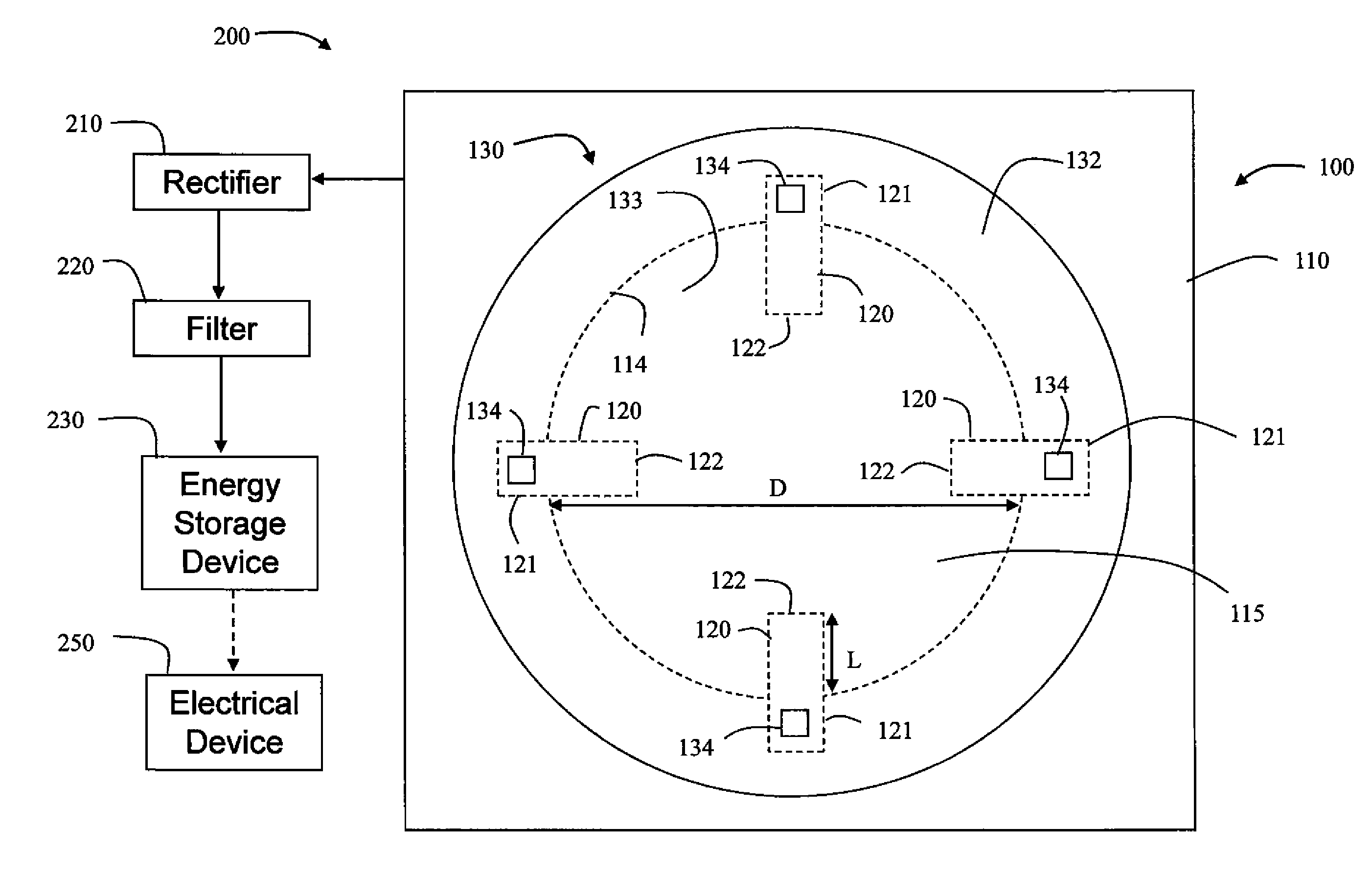
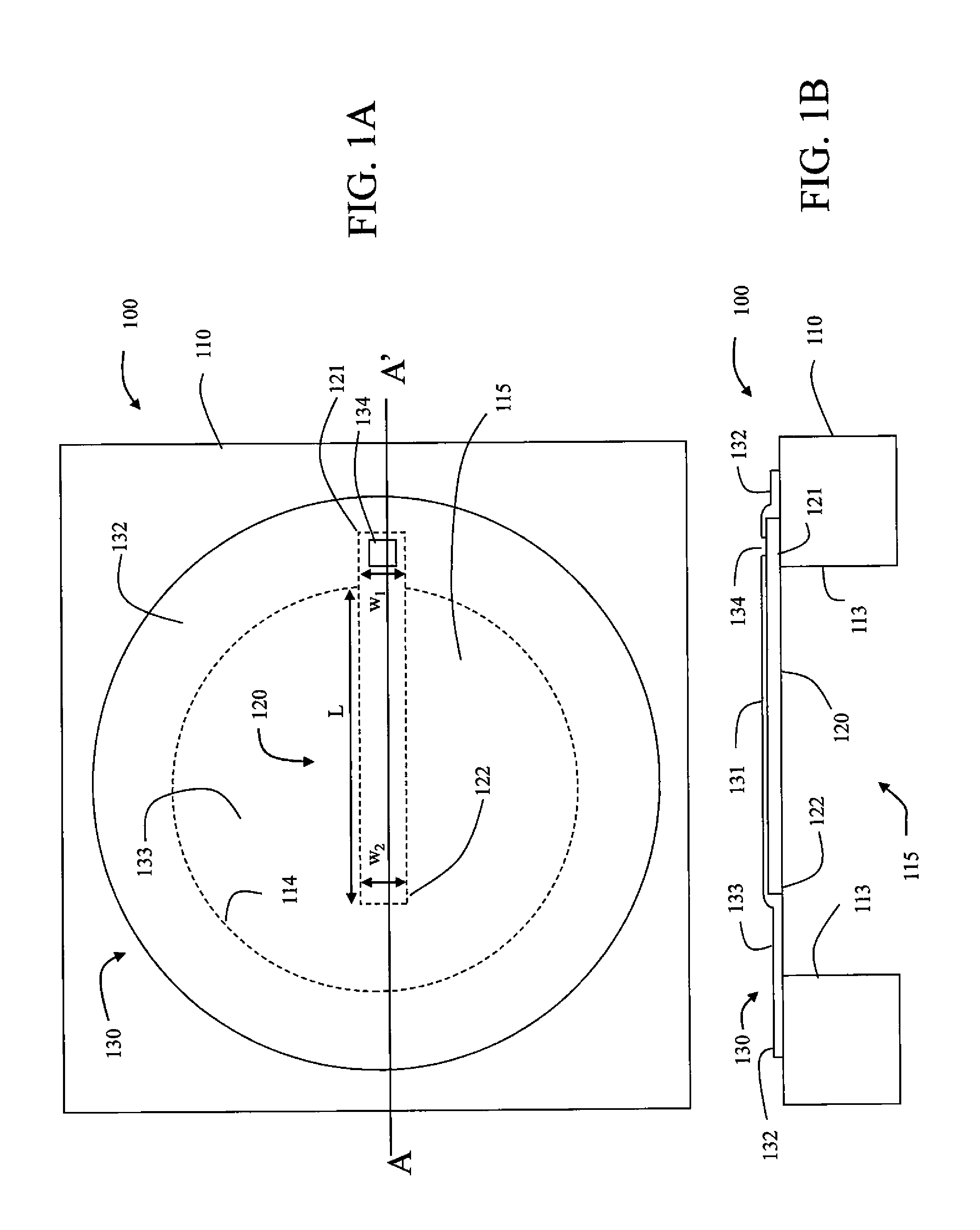
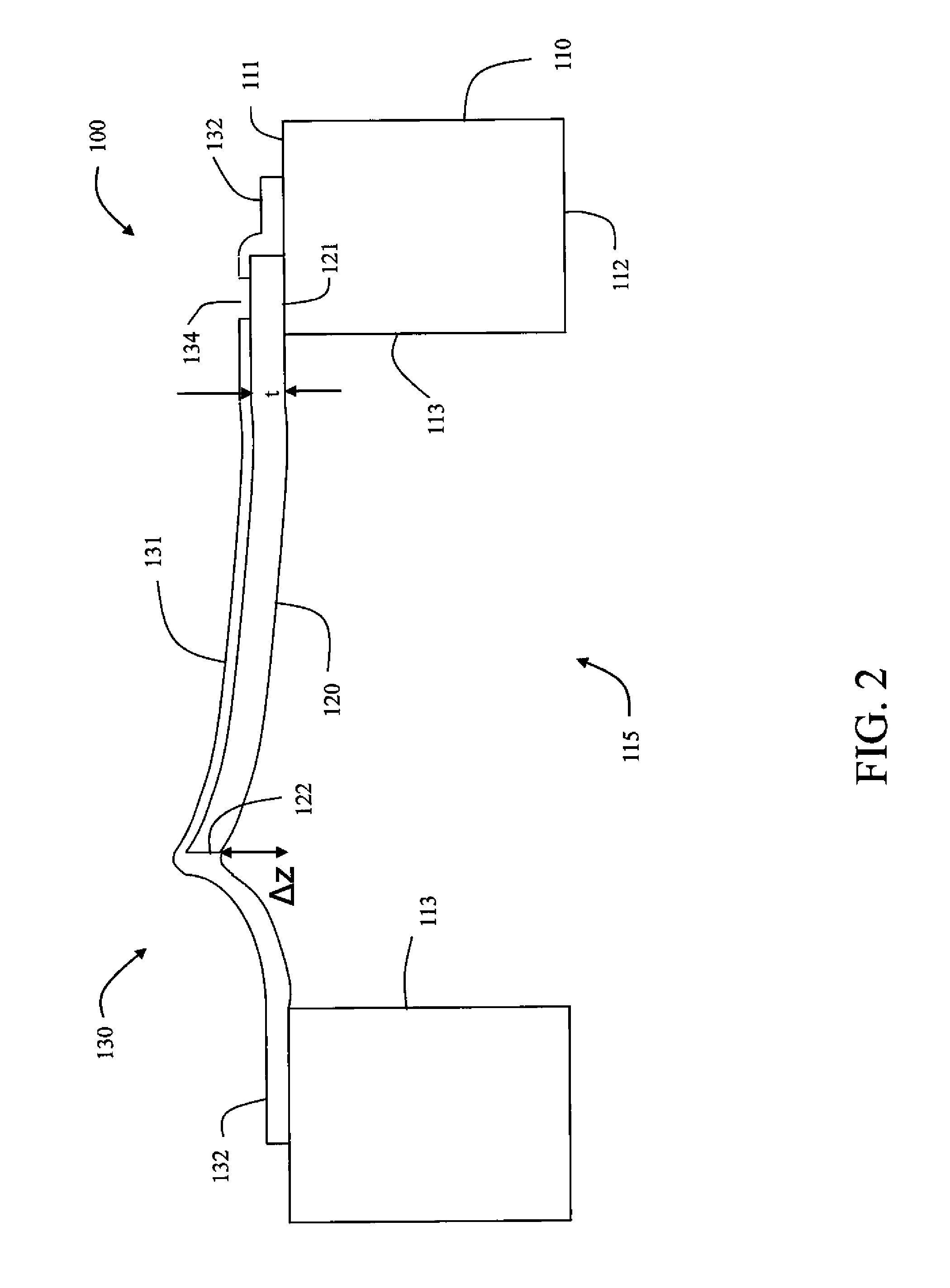
[0029]Embodiments of the present invention include a variety of types of MEMS transducers including a MEMS transducing member and a compliant membrane positioned in contact with the MEMS transducing member, configured such that the MEMS composite transducer can be set into oscillation by excitations such as vibrations or pressure waves in gases, liquids, or solids, in order to convert such periodic excitation into electrical energy. The vibrations can be transmitted to the MEMS composite transducer through, for example, direct or indirect mechanical contact with a vibrating body, or through sound wave propagation. It is to be noted that in some definitions of MEMS structures, ...


PUM


Abstract

An energy harvesting device includes a MEMS composite transducer. The MEMS composite transducer includes a substrate. Portions of the substrate define an outer boundary of a cavity. A MEMS transducing member includes a beam having a first end and a second end. The first end is anchored to the substrate and the second end cantilevers over the cavity. A compliant membrane is positioned in contact with the MEMS transducing member. A first portion of the compliant membrane covers the MEMS transducing member. A second portion of the compliant membrane is anchored to the substrate. The compliant member is configured to be set into oscillation by excitations produced externally relative to the energy harvesting device.

Description

CROSS REFERENCE TO RELATED APPLICATIONS[0001]Reference is made to commonly-assigned, U.S. patent applications Ser. No.______ (Docket 96289), entitled “MEMS COMPOSITE TRANSDUCER INCLUDING COMPLIANT MEMBRANE”, Ser. No. ______ (Docket 96436), entitled “FABRICATING MEMS COMPOSITE TRANSDUCER INCLUDING COMPLIANT MEMBRANE”, Ser. No. ______(Docket K000252), entitled “ENERGY HARVESTING USING MEMS COMPOSITE TRANSDUCER”, all filed concurrently herewith.FIELD OF THE INVENTION[0002]This invention relates generally to energy harvesting devices, and in particular to a MEMS-based transducer that converts motion into electrical energy.BACKGROUND OF THE INVENTION[0003]Micro-Electro-Mechanical Systems (or MEMS) devices are becoming increasingly prevalent as low-cost, compact devices having a wide range of applications. Uses include pressure sensors, accelerometers, gyroscopes, microphones, digital mirror displays, microfluidic devices, biosensors, chemical sensors, and others.[0004]MEMS transducers in...

Claims


Application Information

Patent Timeline
IPC IPC(8): H02K57/00
CPCH02N2/186H01L41/1138H04R17/02H04R2201/003H04R1/265H10N30/308
Inventor HUFFMAN, JAMES D.KNEEZEL, GARY A.
Owner EASTMAN KODAK CO
Learn More