
Fixing Mechanism and Electronic Device Having the Same

a technology of fixing mechanism and electronic device, which is applied in the direction of lighting support device, washstand, instruments, etc., can solve the problem that the fixing structure cannot stably fix the magnet, and achieve the effect of stably fixing the magnetic element, reducing manufacturing costs and assembly time, and simple fixing mechanism structur

Active Publication Date: 2012-10-25
WISTRON CORP
View PDF6 Cites 10 Cited by
  • Summary
  • Abstract
  • Description
  • Claims
  • Application Information

AI Technical Summary

Benefits of technology

[0007]Therefore, an object of the present invention is to provide a fixing mechanism that has a simple structure to reduce manufacturing costs and assembly time thereof and that can stably fix a magnetic element on a base wall.
[0021]Another object of the present invention is to provide an electronic device having a fixing mechanism. The fixing mechanism has a simple structure that can reduce manufacturing cost and assembly hours thereof and that can stably fix a magnetic element to prevent the same from falling off.
[0024]Through the aforesaid technical means, the advantage and efficiency of the electronic device having the fixing mechanism of the present invention reside in that, through the simple structure of the fixing mechanism, manufacturing costs and assembly time thereof can be reduced. Further, the fixing mechanism can stably fix the magnetic element in the receiving space, thereby preventing removal of the magnetic element from the receiving space.

Problems solved by technology

However, because only the first lateral walls cooperatively clamp therebetween the magnet, if the notebook computer falls down accidentally or receives an external impact, the magnet is easily detached from the clamping of the first lateral walls, and moves out of the receiving space via the entry hole.
Thus, the aforesaid magnet fixing structure cannot stably fix the magnet.

Method used


Image

  • Fixing Mechanism and Electronic Device Having the Same
  • Fixing Mechanism and Electronic Device Having the Same
  • Fixing Mechanism and Electronic Device Having the Same

Examples


Embodiment Construction

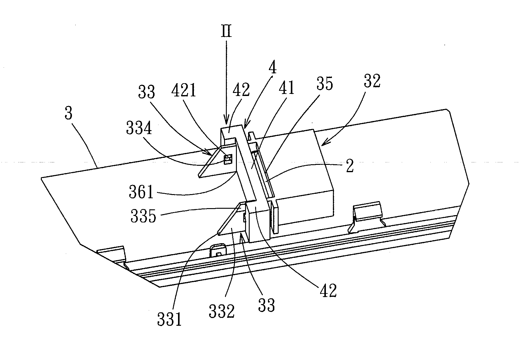
[0043]The above-mentioned and other technical contents, features, and effects of this invention will be clearly presented from the following detailed description of five embodiments in coordination with the reference drawings. Through description of the concrete implementation method, the technical means employed and the effectiveness to achieve the predetermined purposes of the present invention will be thoroughly and concretely understood. However, the enclosed drawings are used for reference and description only, and are not used for limiting the present invention.

[0044]Before this invention is described in detail, it should be noted that, in the following description, similar elements are designated by the same reference numerals.

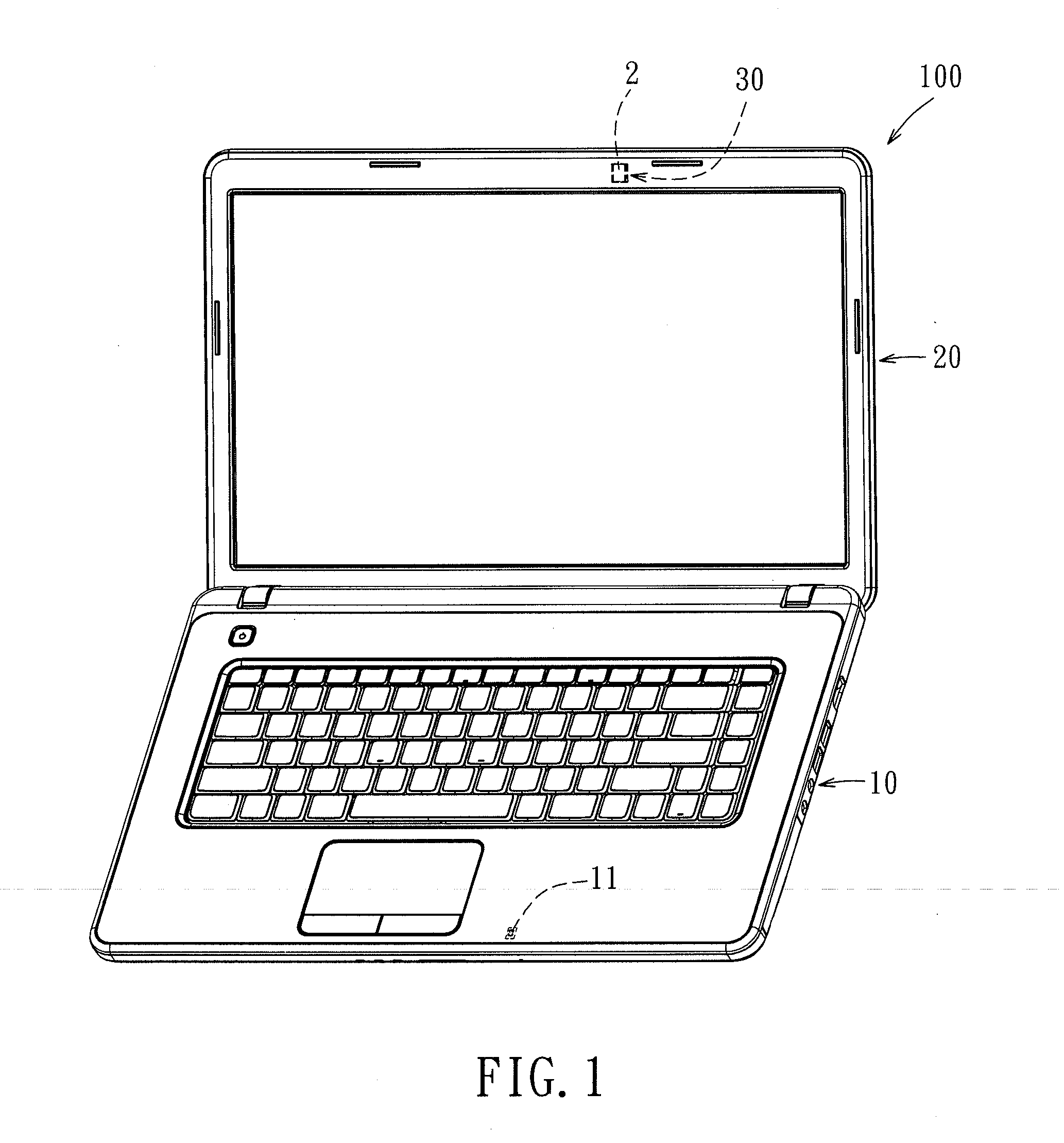
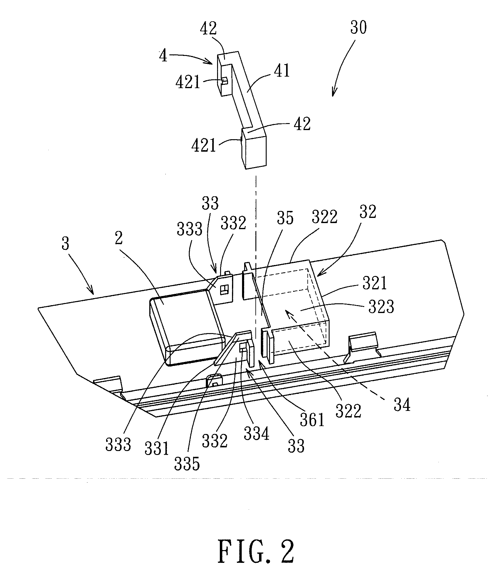
[0045]Referring to FIGS. 1 to 4, an electronic device 100 according to the first embodiment of the present invention comprises a first body 10, and a second body 20 connected pivotally to a lateral side of the first body 10. In this embodiment, the elec...


PUM


Abstract

A fixing mechanism for fixing a magnetic element on a base wall includes a frame, a retaining member, and a blocker. The frame is adapted to be connected to and is adapted to cooperate with the base wall to define a receiving space for receiving the magnetic element, and an opening communicating with the receiving space for entry of the magnetic element into the receiving space along a first assembly direction. The retaining member is adapted to be connected to the base wall in proximity to the frame. The blocker is engaged to the retaining member, and blocks the opening.

Description

CROSS REFERENCE TO RELATED APPLICATION[0001]This application claims priority of Taiwanese Patent Application No. 100114061 filed on Apr. 22, 2011, the disclosure of which is incorporated herein by reference.BACKGROUND OF THE INVENTION[0002]1. Field of the Invention[0003]The invention relates to a fixing mechanism and an electronic device having the same, and more particularly to a fixing mechanism for fixing a magnetic element on a base wall and an electronic device having the same.[0004]2. Description of the Related Art[0005]In a magnet fixing structure and a notebook computer disclosed in Taiwanese Patent No. M348452, the magnet fixing structure includes a base wall, two opposite first lateral walls having bottom ends connected to the base wall, and a second lateral wall having a bottom end connected to the base wall and two opposite lateral ends connected respectively to one lateral ends of the first lateral walls. The first and second lateral walls cooperatively define a receivi...

Claims


Application Information

Patent Timeline
Patent Type & Authority Applications(United States)
IPC IPC(8): H05K7/14F16M13/02
CPCG06F1/1679
Inventor LIANG, CHEN-YICHUANG, CHENG-HSIANGCHEN, CHUN-CHIENBAI, SHUN-DEKAO, SAN-PAO
Owner WISTRON CORP
Learn More