Demodulator of a frequency-modulated electrical signal

a frequency-modulated, electrical signal technology, applied in the direction of oscillator, angle demodulation by sloping amplitude/frequency, electrical apparatus, etc., can solve the problems of bulky and complex features of all known demodulators, and achieve the effect of increasing the sensitivity of the demodulator

Inactive Publication Date: 2012-10-25
COMMISSARIAT A LENERGIE ATOMIQUE ET AUX ENERGIES ALTERNATIVES
View PDF0 Cites 0 Cited by
  • Summary
  • Abstract
  • Description
  • Claims
  • Application Information

AI Technical Summary

Benefits of technology

[0038]using a radiofrequency oscillator synchronizable with the frequencies αf1 and α

Problems solved by technology

However, all these known demodulators have the c

Method used


Image

  • Demodulator of a frequency-modulated electrical signal
  • Demodulator of a frequency-modulated electrical signal
  • Demodulator of a frequency-modulated electrical signal

Examples


Embodiment Construction

[0060]In these figures, the same references are used to designate the same elements.

[0061]Here below in this description, the characteristics and functions well known to those skilled in the art are not described in detail.

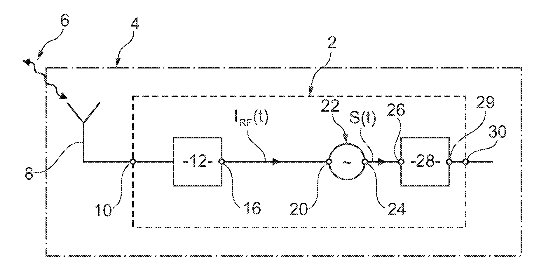
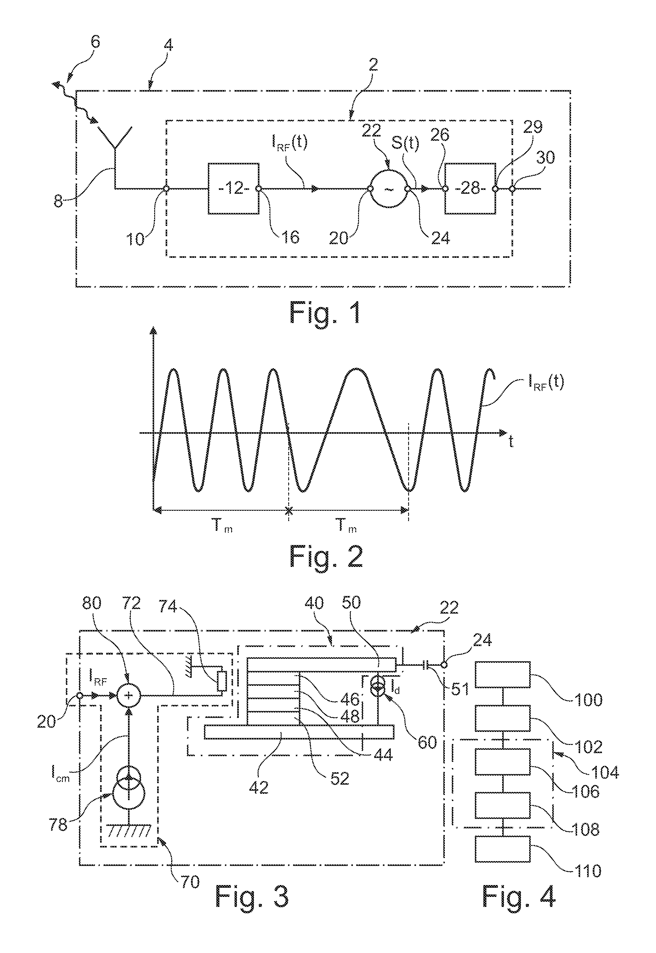
[0062]FIG. 1 shows a demodulator 2 of a frequency-modulated electrical signal. Here, the demodulator 2 is described in the particular case where it forms part of an apparatus 4 capable of receiving the frequency-modulated signal through a wireless link 6. For example, the apparatus 4 is a portable telephone and the link 6 is a radio link.

[0063]The apparatus 4 is equipped with an antenna 8 to set up the wireless link 6. The antenna 8 converts the radio signal into an electrical signal that is transmitted to a terminal 10 for acquisition of the electrical signal of the demodulator 2. Between the antenna 8 and the terminal 10, the apparatus 4 can have different electronic blocks that have not been shown in order to simplify FIG. 1.

[0064]In the signal received by the ...


PUM


Abstract

A demodulator of an FM signal modulated about a carrier frequency with a modulation frequency has an RF oscillator configured to be synchronized, under identical conditions of operation, with oscillations at first and second frequencies used in the FM signal to encode respective pieces of information. The oscillator has a magnetoresistive device; and a low-pass filter connected to an output electrode of the magnetoresistive device to filter an oscillating signal, generated by the oscillator and to a rendering terminal to provide, as a demodulated electrical signal, the filtered signal, the cut-off frequency fc at −3 dB of this filter being strictly lower than the frequency and higher than the modulation frequency.

Description

BACKGROUND OF THE INVENTION[0001]The invention pertains to a demodulator of an electrical signal that is frequency-modulated about a carrier frequency fp with a modulation frequency fm. An object of the invention is also a method for demodulating a frequency-modulated electrical signal of this kind.[0002]In frequency-modulated electrical signals, a piece of information is encoded on a frequency. For example, such signals are sent or received by a portable telephone or a radio system.PRIOR ART[0003]There is therefore a very large number of demodulators used at the present time to demodulate these signals. For example, the following different types of demodulators are known:[0004]in-phase quadrature demodulators,[0005]synchronous demodulators,[0006]etc.[0007]All these known demodulators comprise:[0008]an acquisition terminal at which the frequency-modulated signal is received, and[0009]a rendering terminal at which the frequency-demodulated electrical signal is rendered.[0010]However,...

Claims


Application Information

Patent Timeline
IPC IPC(8): H04B1/16
CPCH03B15/00H03D3/26H03B15/006
Inventor QUINSAT, MICHAELCYRILLE, MARIE-CLAIREEBELS, URSULAMICHEL, JEAN-PHILIPPE
Owner COMMISSARIAT A LENERGIE ATOMIQUE ET AUX ENERGIES ALTERNATIVES
Why Eureka
Try Eureka