System and method for controlling power consumption of an in vivo device

a technology power consumption, applied in the field of system and method for controlling power consumption of in vivo devices, can solve the problems of limited space available for capsule components including their energy source, size of energy source, and limitation of power available for capsule operation, etc., and achieve the effect of controlling energy consumption

Active Publication Date: 2012-10-25
GIVEN IMAGING LTD
View PDF7 Cites 27 Cited by
  • Summary
  • Abstract
  • Description
  • Claims
  • Application Information

AI Technical Summary

Benefits of technology

[0007]A method and device may control energy consumption of in an in vivo imaging device by determining or estimating an amount of energy needed to capture images at a frame rate until the passage of the device through a predetermined region of the GI tract, and alter or limit the frame capture rate accordingly.

Problems solved by technology

For it to be swallowable, an autonomous in vivo capsule must not exceed a certain girth and length, which in turn may limit the space available for the capsule components including its energy source.
The limitation on the size of the energy source may translate into a limitation on the power available for the operation of the capsule.
A propelled capsule may complete the passage in a shorter time, but may require more energy to do it.
The device may move unevenly inside the passages or cavities of the body.
However, when the rate of image capture and transmission is increased, so too is the power consumption.
In some cases, variable transmission rates that are too high may deplete the power resources of the device.
If the energy resources are depleted before the device is expelled from the body, regions of the GI tract may not be imaged.

Method used


Image

  • System and method for controlling power consumption of an in vivo device
  • System and method for controlling power consumption of an in vivo device
  • System and method for controlling power consumption of an in vivo device

Examples


example 1

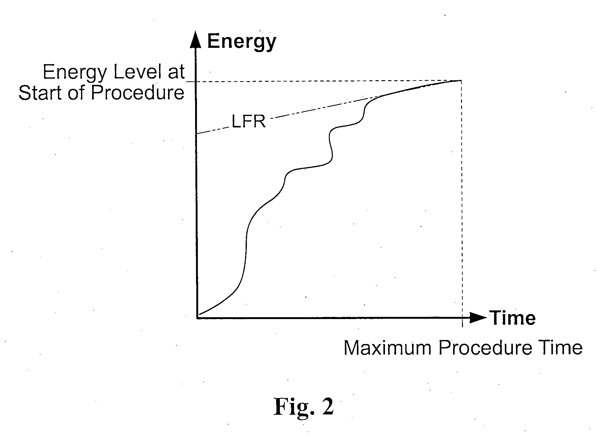
[0085]In a first example, power source 145 may have substantially no energy loss due to storage, e.g., when device 140 is immediately used, (StorageEnergyReduction==0). The energies used to capture each frame in each of modes 0-4 are described in Table 1. A clock in or operated by for example processor 147 (e.g., a 8.1 MHz clock) may measure the time in which device 140 operates each mode, e.g., as follows:[0086]7 min in Mode 0 (1680 frames),[0087]30 minutes in Mode 1 (1440 frames),[0088]1 hour in Mode 2 (14400 frames),[0089]57.4917 minutes in Mode 3 (124182 frames), and[0090]a total estimated procedure time of 9 hours.

A processor may substitute the values above into equation (1), for example, as follows:

52-0-(1.09933600*1680+0.60263600*1440+1.09933600*14400+0.53913600*124182)-(9-2.5749)*1.0993360014*3600=52-(1.09933600*1680+0.60263600*1440+1.09933600*14400+0.53913600*124182)-(9-2.5749)*4*1.0993=0.000049

[0091]The resulting equation (1) has a value very close to zero, though greater ...

example 2

[0118]In a second example, power source 145 may suffer an energy loss due to storage, e.g., when device 140 has been stored for 12 months. The average energies used to capture each frame in each of modes 0-4 are listed in Table 1. A clock in processor 147 (e.g., a 8.1 MHz clock) may measure the time in which device 140 operates each mode, e.g., as follows:[0119]7 min in Mode 0 (1680 frames),[0120]30 minutes in Mode 1 (1440 frames), and[0121]a total estimated procedure time of 9 hours.

A processor may calculate the BaseEnergy (mAh) of device 140, e.g., as follows:

BaseEnergy=BatteryFullCap-StorageEnergyReduction-∑iEngSti*Counteri=52-(0.52+0.219)*12-1.09933600*1680-0.60263600*1440=42.378mAh

[0122]The processor may determine the maximal number, X, of frames that may be captured at the higher than minimum frame rate, e.g., of Mode 3, without depleting the energy reserve, when device 140 was stored for 12 months, e.g., by substituting values into equation (4) as follows.

X≦BaseEnergy-Procedu...

example 3

[0124]In a third example, power source 145 may have substantially no energy loss due to storage, e.g., when device 140 is used soon after manufacture, (StorageEnergyReduction==0). The energies used to capture each frame in each of modes 0-4 are listed in Table 1. A clock in processor 147 (e.g., a 8.1 MHz clock) may measure the time in which device 140 operates each mode, e.g., as follows:[0125]7 min in Mode 0 (1680 frames),[0126]30 minutes in Mode 1 (1440 frames), and[0127]a total estimated procedure time of 9 hours.

If there is no energy loss due to storage, the BaseEnergy (mAh) of device 140 may be calculated, e.g., as follows:

BaseEnergy=BatteryFullCap-StorageEnergyReduction-∑iEngSti*Counteri=52-0-1.09933600*1680-0.60263600*1440=51.246mAh

With no energy depletion due to storage, e.g., values may be substituted into equation (4) as follows:

X≦BaseEnergy-ProcedureMaxTime-TAFRStartTLFR*EngStLFREngStHFR-THFRTLFR*EngStLFRX=51.246-9-0.61670.25 / 3600*1.0993 / 36000.5391 / 3600-436*1.0993 / 3600=36...


PUM


Abstract

A method and device may control energy consumption of in an in vivo imaging device by determining or estimating an amount of energy needed to capture images at a frame rate until a complete passage of the device through a predetermined region of the gastrointestinal tract, and alter or limit the frame capture rate accordingly.

Description

BACKGROUND OF THE INVENTION[0001]Devices and methods for performing in vivo imaging of passages or cavities within a body are well known in the art. Such devices may include, inter alia, endoscopic imaging systems and devices, for example, an in vivo capsule, for performing imaging in various internal body cavities.[0002]For it to be swallowable, an autonomous in vivo capsule must not exceed a certain girth and length, which in turn may limit the space available for the capsule components including its energy source. The limitation on the size of the energy source may translate into a limitation on the power available for the operation of the capsule.[0003]The passage of an autonomous in vivo capsule through the peristalsis of the gastrointestinal (GI) tract may take several hours. A propelled capsule may complete the passage in a shorter time, but may require more energy to do it. Furthermore, the capsule may travel for several hours during the gastrointestinal tract before it reac...

Claims


Application Information

Patent Timeline
Patent Type & Authority Applications(United States)
IPC IPC(8): A61B1/045
CPCA61B1/00029A61B1/00032A61B2560/0209A61B1/041A61B1/045A61B1/00036
Inventor KHAIT, SEMIONHORN, ELINISANI, MICHAZINATY, OFRA
Owner GIVEN IMAGING LTD
Why Eureka
Try Eureka