
Occluder For Occluding an Atrial Appendage and Production Process Therefor

Active Publication Date: 2012-10-25
OCCLUTECH HLDG
View PDF95 Cites 111 Cited by
  • Summary
  • Abstract
  • Description
  • Claims
  • Application Information

AI Technical Summary

Benefits of technology

[0018]It is an object of the present invention to overcome the above-mentioned disadvantages of the conventional processes and devices and potentially to specify a cost-saving, patient friendly and patient secure solution.

Problems solved by technology

The occlusion device is suited in order to permanently occlude an opening having a dynamic blood flow, and to this end has a special construction and is not suitable for atrial appendage occlusions.
If a patient is suffering from “atrial fibrillation” of the heart, particular embolism-related problems may appear.
A considerable risk in case of formation of atrial thrombi as result of atrial fibrillation consists in the fact that such thrombi can be carried along with the bloodstream and reach the arterial circulation.
However, bringing about the anticoagulation of the blood with dicoumarol, is likewise not without risk.
These devices, inter alia, have the disadvantage that relatively large insertion locks of up to 14 F internal diameter are needed for the implantation.
Further devices, such as of Amplatz PCT / US 2005 / 010551, according to the PLAATO method (PLAATO=Percutaneus Left Atrial Appendage Transcatheter) and Watchman occluder do not cope with the correct specified positioning.
However, these devices lack flexibility due to the necessary attachment of the cover to the cylinder.
Moreover, clamps hold both ends of a cut braid together, which clamps may protrude from the device, lead to undesired side effects, such as thromboembolic complications.
In addition, an aneurysm is substantially different from an atrial appendage and the aneurysm occlusion device is not suited for occluding an atrial appendage.
Therefore the anchoring of the aneurysm occlusion device of U.S. Pat. No. 6,168,622 would not be sufficient to fulfill the requirements of an atrial appendage occlusion device.

Method used


Image

  • Occluder For Occluding an Atrial Appendage and Production Process Therefor
  • Occluder For Occluding an Atrial Appendage and Production Process Therefor
  • Occluder For Occluding an Atrial Appendage and Production Process Therefor

Examples


Embodiment Construction

[0046]Specific embodiments of the invention will now be described with reference to the accompanying drawings. This invention may, however, be embodied in many different forms and should not be construed as limited to the embodiments set forth herein; rather, these embodiments are provided so that this disclosure will be thorough and complete, and will fully convey the scope of the invention to those skilled in the art. The terminology used in the detailed description of the embodiments illustrated in the accompanying drawings is not intended to be limiting of the invention. In the drawings, like numbers refer to like elements.

[0047]Other different application-specific designs of the occlusion device are also conceivable. The designs given serve as description of embodiments of occlusion devices and, in particular, are not intended to restrict the scope of protection of the invention in any manner.

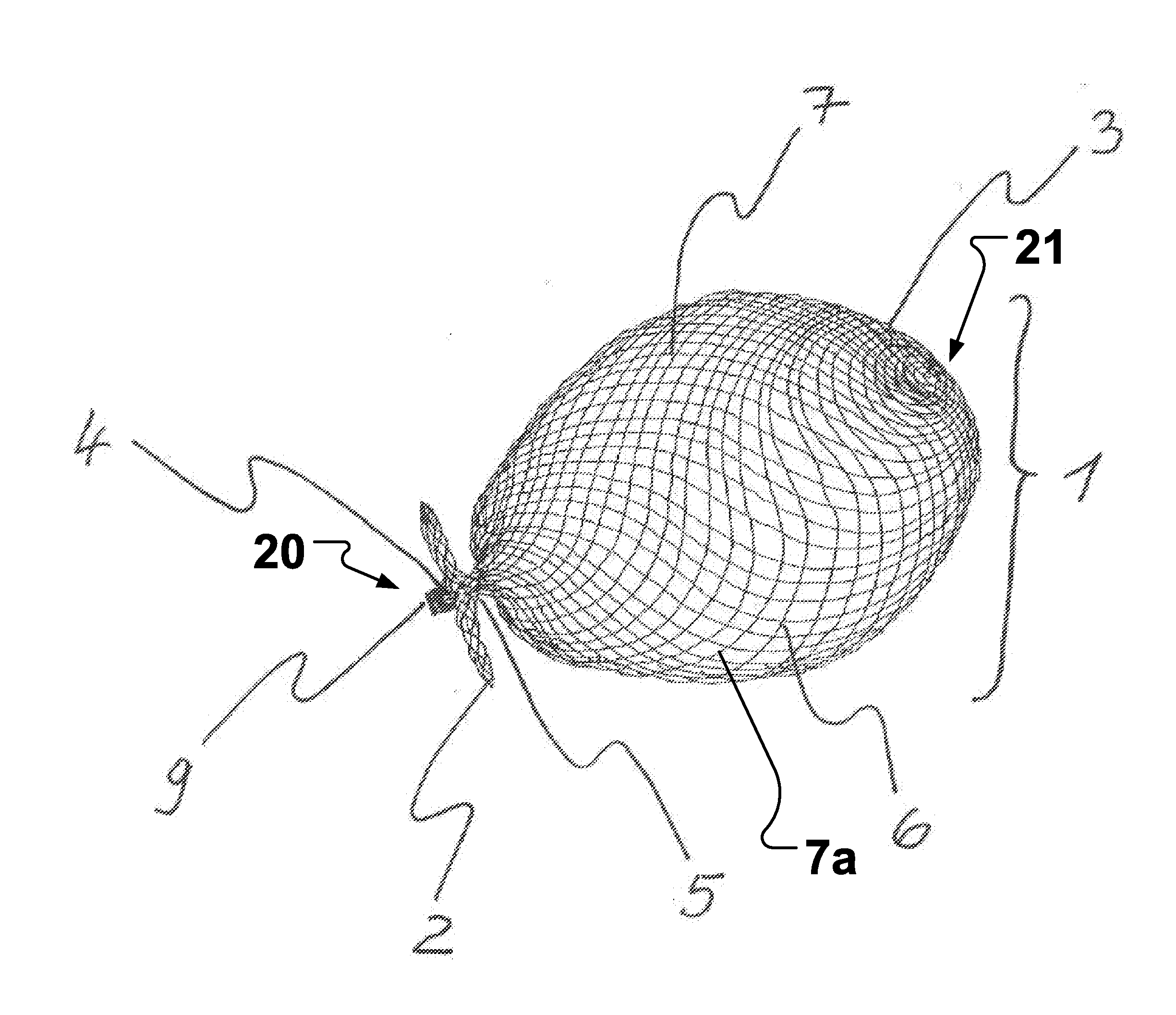
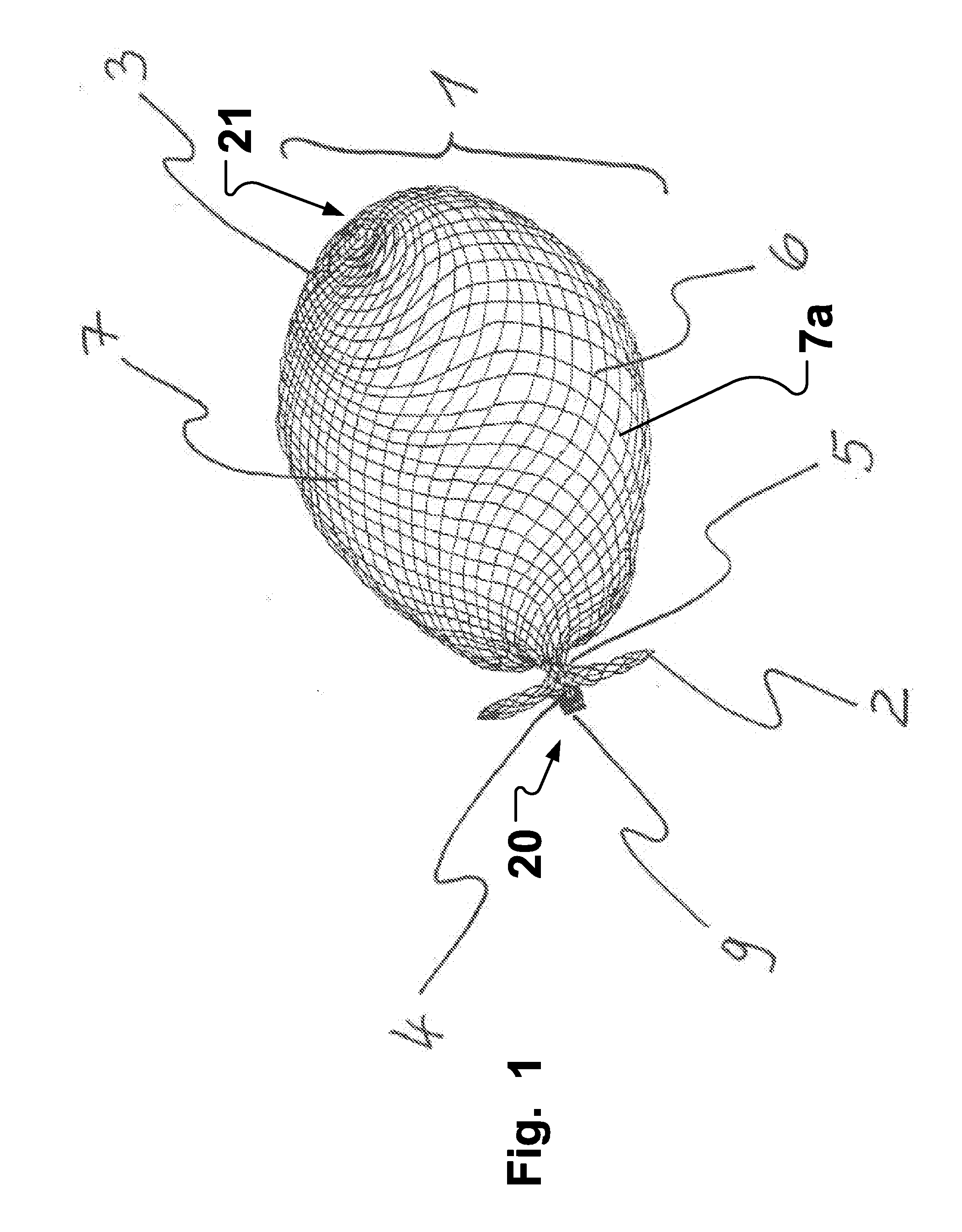
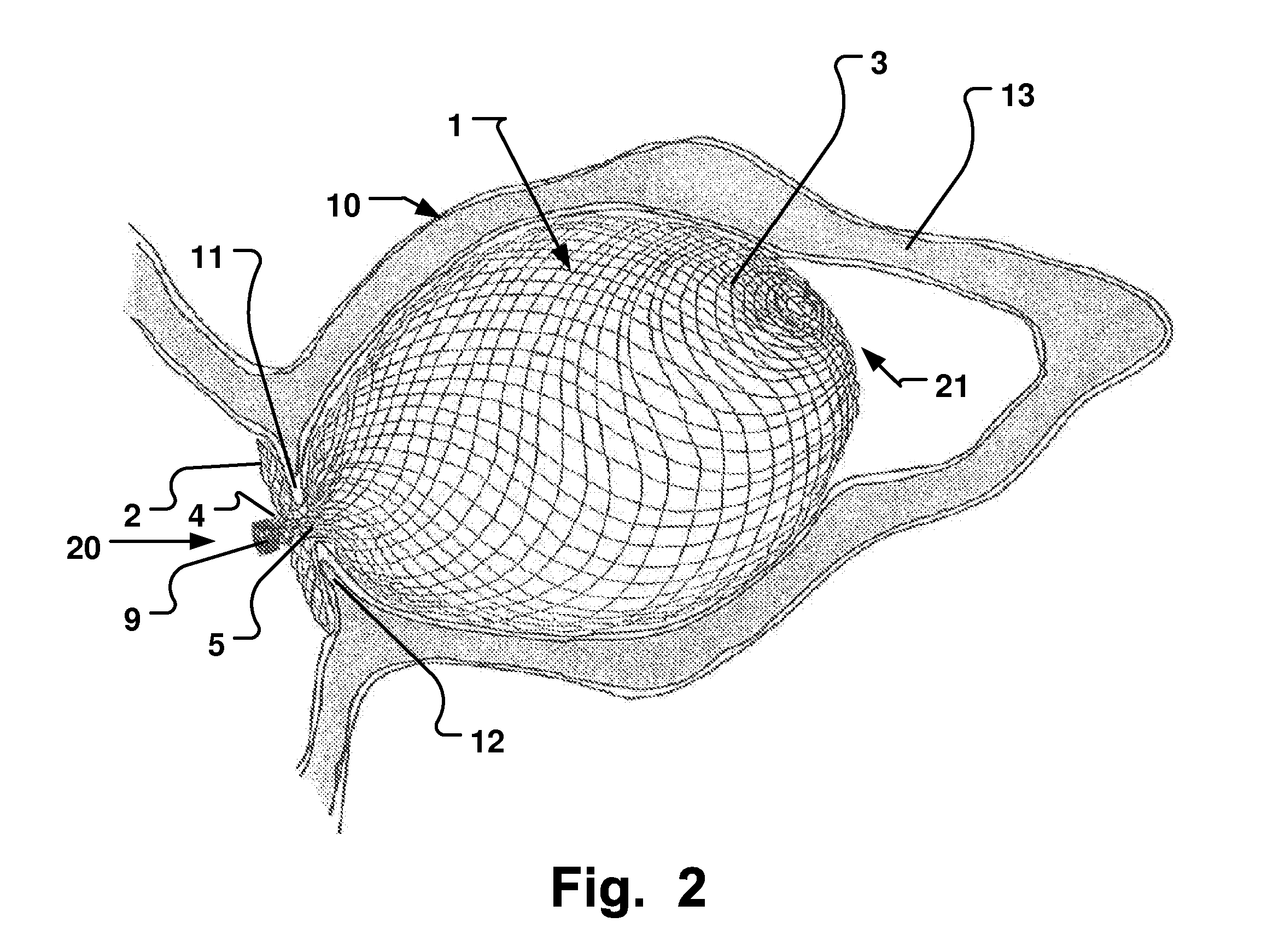
[0048]FIG. 1 shows a side view of an embodiment of a self-expandable atrial appendage ...


PUM


Abstract

An occlusion device and a production process for it are described. The occlusion device consists of a mesh or braiding of at least one wire or thread wherein the occlusion device has been given a suitable design using a reshaping and / or heat-treatment process, is self-expandable, and is configured for secure anchoring in an atrial appendage of the left or right atrium of a heart. The occlusion device comprises a proximal retention region on a proximal end of the occlusion device a distal retention region and a central region between the proximal retention region and said distal retention region and wherein the occlusion device has a closed distal end without a holder, and wherein the occlusion device is at least partly of essentially spherical form, and hollow.

Description

RELATED APPLICATIONS[0001]This application is a continuation of U.S. patent application Ser. No. 12 / 595,601 deposited Oct. 12, 2009 entitled Occluder For Occluding an Atrial Appendage and Production Process Therefor, which is a U.S. National Stage application of International Patent Application No. PCT / EP2008 / 054622, International Filing Date Apr. 16, 2008, entitled Occluder For Occluding An Atrial Appendage And Production Process Therefor, which in turn claims priority to European patent application no. 07106278.0 filed Apr. 16, 2007 entitled Occluder zum Verschliessen eines Herzohres und Herstellungsverfahren dafur, and to U.S. Provisional Application Ser. No. 60 / 913,236 filed Apr. 20, 2007 entitled Occluder zum Verschliessen eines Herzohres und Herstellungsverfahren dafur, all of which are hereby incorporated herein by reference.FIELD OF THE INVENTION[0002]The present invention relates to a self-expandable occlusion device for occluding an atrial appendage, consisting of a networ...

Claims


Application Information

Patent Timeline
IPC IPC(8): A61M29/00D04C1/00
CPCA61B17/0057A61B17/12022A61B17/12122A61B17/12172A61B2017/00867A61B2017/00592A61B2017/00597A61B2017/00606A61B2017/00615A61B2017/00575A61B17/12031A61B17/12168A61B2017/12054
Inventor FIGULLA, HANS-REINERMOSZNER, ROBERTOTTMA, RUDIGERSCHRADER, R.SCHMIDT, KATHRIN
Owner OCCLUTECH HLDG
Learn More