
Power drill

a power drill and drive rod technology, applied in the field of power drills, can solve the problems of clamping force, blockage of the rotational drive member with respect to the threaded stem element, etc., and achieve the effect of reliable displacement of the spindle rod

Active Publication Date: 2012-11-01
ROHM GMBH
View PDF8 Cites 11 Cited by
  • Summary
  • Abstract
  • Description
  • Claims
  • Application Information

AI Technical Summary

Benefits of technology

[0008]It has been shown to be useful when a gear arrangement, preferably a planetary-gear transmission, is provided between the motor and the drive sleeve. This enables the highest possible torques to be transmitted to the drive spindle and, in the drilling configuration, also to the threaded stem element.
[0021]Finally, it has been shown to be preferable when the adjusting sleeve has at least one adjusting element that interacts with the driver ring, as this ensures a guided and reliable displacement of the spindle rod.

Problems solved by technology

In addition, the compact design of the power drill guarantees that, in the drilling configuration, rotation of the threaded drive member with respect to the threaded stem element is blocked.
Furthermore, a limitation of the clamping force, such as is often provided with self-tightening drill chucks, is no longer necessary.

Method used


Image

  • Power drill
  • Power drill
  • Power drill

Examples


Embodiment Construction

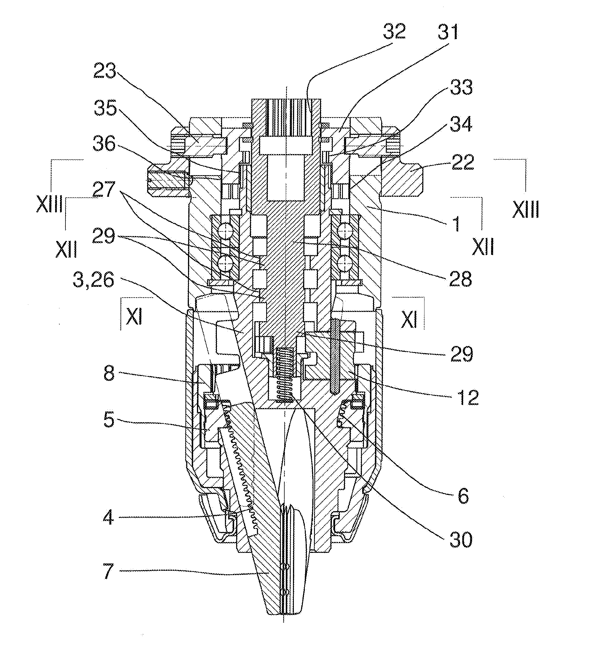
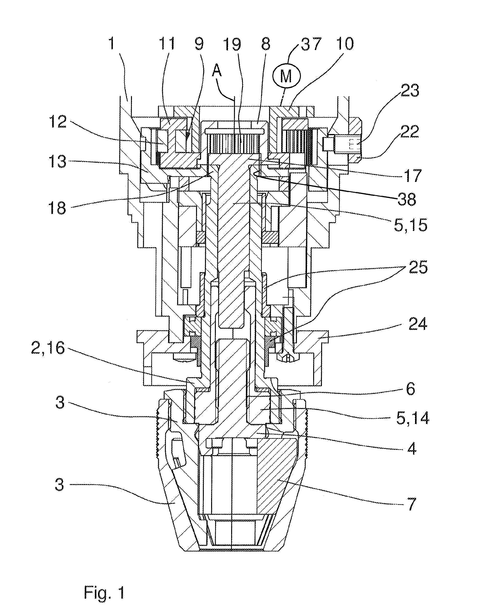
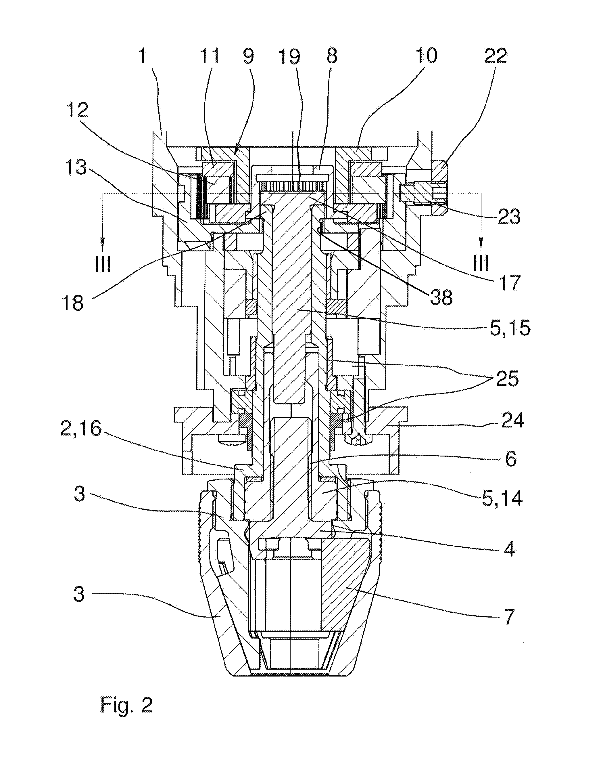
[0031]As seen in FIGS. 1 to 3 a first preferred embodiment of the power drill consisting of a power drill having a motor 37 and a drive spindle 2 rotatable in a housing 1 about its axis A and fixed at its front to a chuck body 3 in which jaws 7 can be shifted axially and radially by a threaded connection 6 formed between a threaded drive member 4 and a threaded stem element 5. The jaws 7 can shift axially and radially in the chuck body 3 but cannot move angularly relative to it or to the drive member 4. On the other hand, the stem element 5 can as described below rotate relative to the chuck body 3 but not move axially or radially therein or can be rotationally fixed to the chuck body 3.

[0032]In addition as also shown in FIG. 3, a planetary-gear transmission has a sun gear 10 that is rotatable about the axis A by the motor 37, five planet gears 12 meshing radially inward with the sun gear 10 and radially outward with a ring gear 13 that is rotationally fixed on the housing 1 but as ...


PUM

PropertyMeasurementUnit
transmissionaaaaaaaaaa
relative rotationaaaaaaaaaa
rotationaaaaaaaaaa

Abstract

A drilling apparatus has a housing, a motor in the housing, a drive spindle rotatable about an axis on the housing, a chuck body, and a plurality of jaws shiftable in the chuck body. First and second elements interconnected by a screw thread and engaged between the body and the jaws for shifting the jaws on the housing. A drive sleeve rotationally fixed to the first element is drivable by the motor.

Description

FIELD OF THE INVENTION[0001]The present invention relates to a power drill.BACKGROUND OF THE INVENTION[0002]A typical power drill has a motor and a drive spindle rotatably mounted in a housing, and a drilling chuck with a chuck body in which displaceable jaws are guided by a threaded connection formed between a threaded drive member and a threaded stem element.[0003]A drilling chuck of the kind described above is disclosed in DE 10 2009 026 075 (U.S. application Ser. No. 13 / 302,037 filed 4 Mar. 2012). It has a housing, a tubular drive spindle extending forward along an axis from the housing, a drive motor in the housing and permanently connected to the spindle for rotating the spindle about the axis, and a chuck body carried on the spindle outside the housing. An internally threaded sleeve element is provided in the spindle, and a driver, sleeve, and holder carried on the chuck body form a plurality of angularly spaced angled guides receiving respective jaws axially rearwardly brace...

Claims


Application Information

Patent Timeline
Patent Type & Authority Applications(United States)
IPC IPC(8): B23B31/12B23B47/04
CPCB23B31/1238B23B31/1253Y10T279/17B23B2260/07Y10T279/17615B23B2231/06B23B31/102B23B31/26Y10T279/27Y10T279/3451Y10T408/65
Inventor SCHENK, PETER
Owner ROHM GMBH
Learn More