Hose Repair Clamp

a technology for repairing clamps and hoses, applied in the direction of hose connections, pipe elements, pipe connection arrangements, etc., can solve the problems of high-pressure hydraulic hoses failing, costing time and money, etc., and achieve the effect of minimizing leakage and minimizing leakag

Inactive Publication Date: 2012-11-01
HOSEBEE
View PDF16 Cites 21 Cited by
  • Summary
  • Abstract
  • Description
  • Claims
  • Application Information

AI Technical Summary

Benefits of technology

[0002]The device according to the present disclosure comprises two clamp portions which “sandwich” a hose at the point of leakage. A semi-cylindrical channel extending along the inner surface of the clamp portions receives the hose and a plurality of fasteners fixes the two clamp portions together. Barbs extending into the channel protrude into the hose and seal against the outside rubber layer of the hose. Because the outside rubber layer of the hose is resilient, the barbs further cause the outside rubber layer to press against the inner hose layers. The compression of the barbs into the hose minimizes leakage longitudinally along the hose. Ga

Problems solved by technology

High pressure hydraulic hoses failing in use in the “field” cost time and money.
Typically, a user must replace a leaky hydra

Method used


Image

  • Hose Repair Clamp
  • Hose Repair Clamp
  • Hose Repair Clamp

Examples


Embodiment Construction

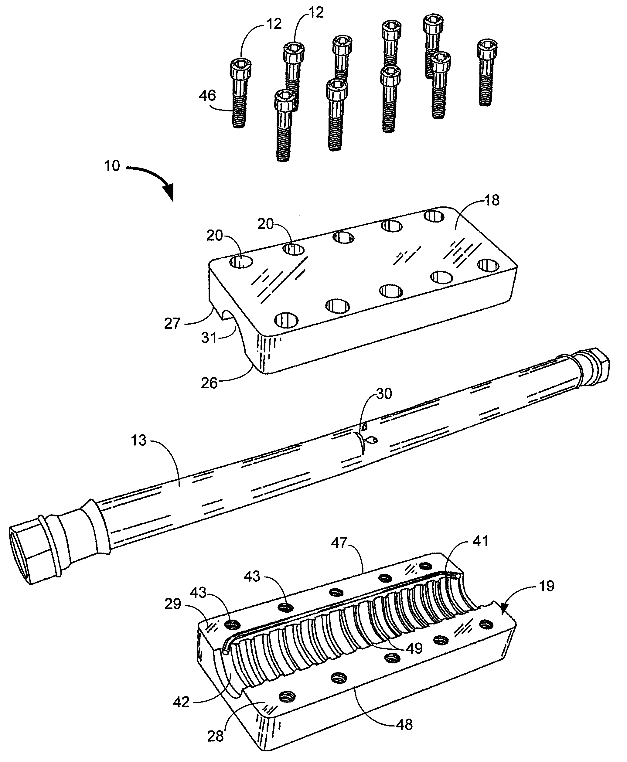
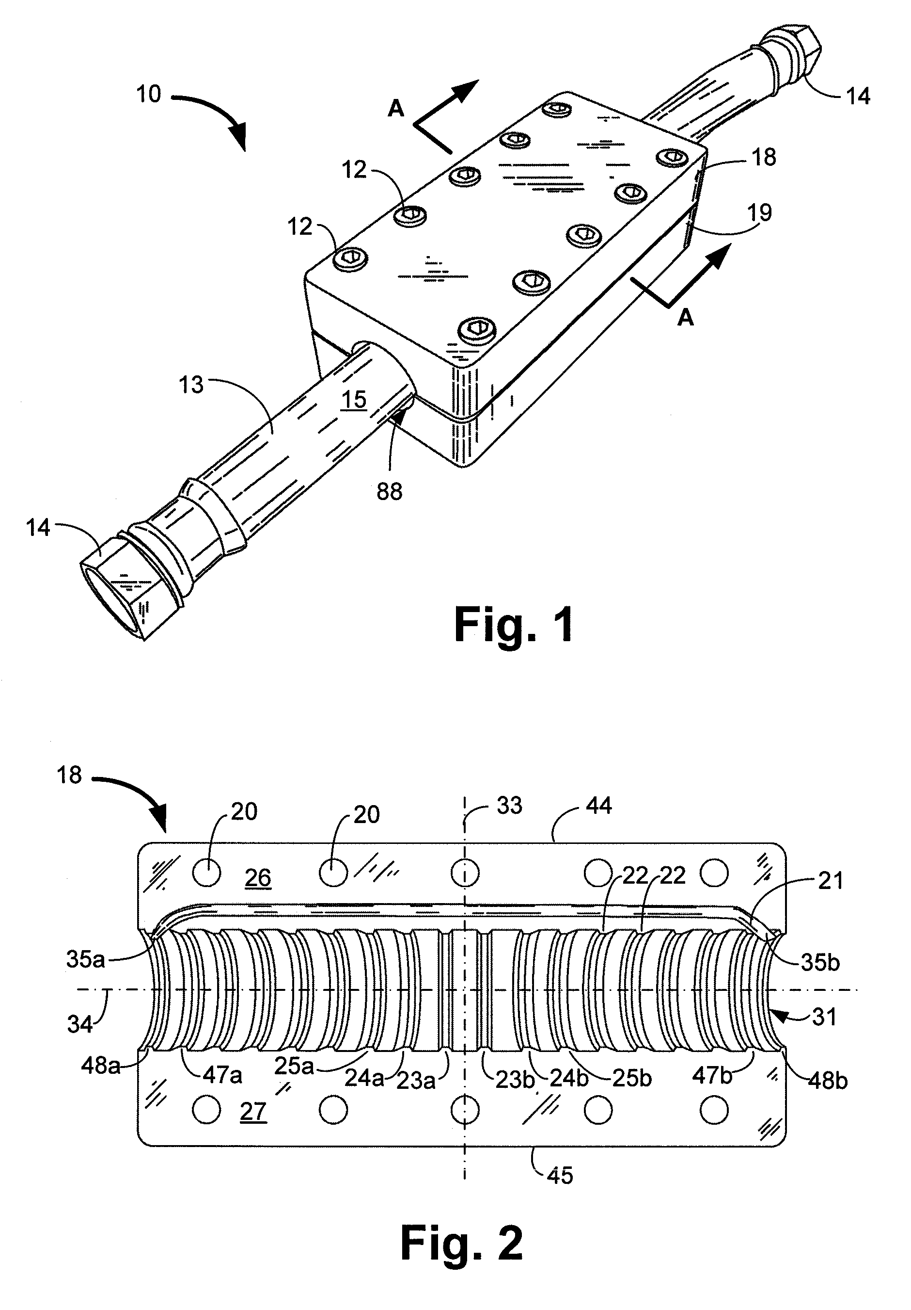
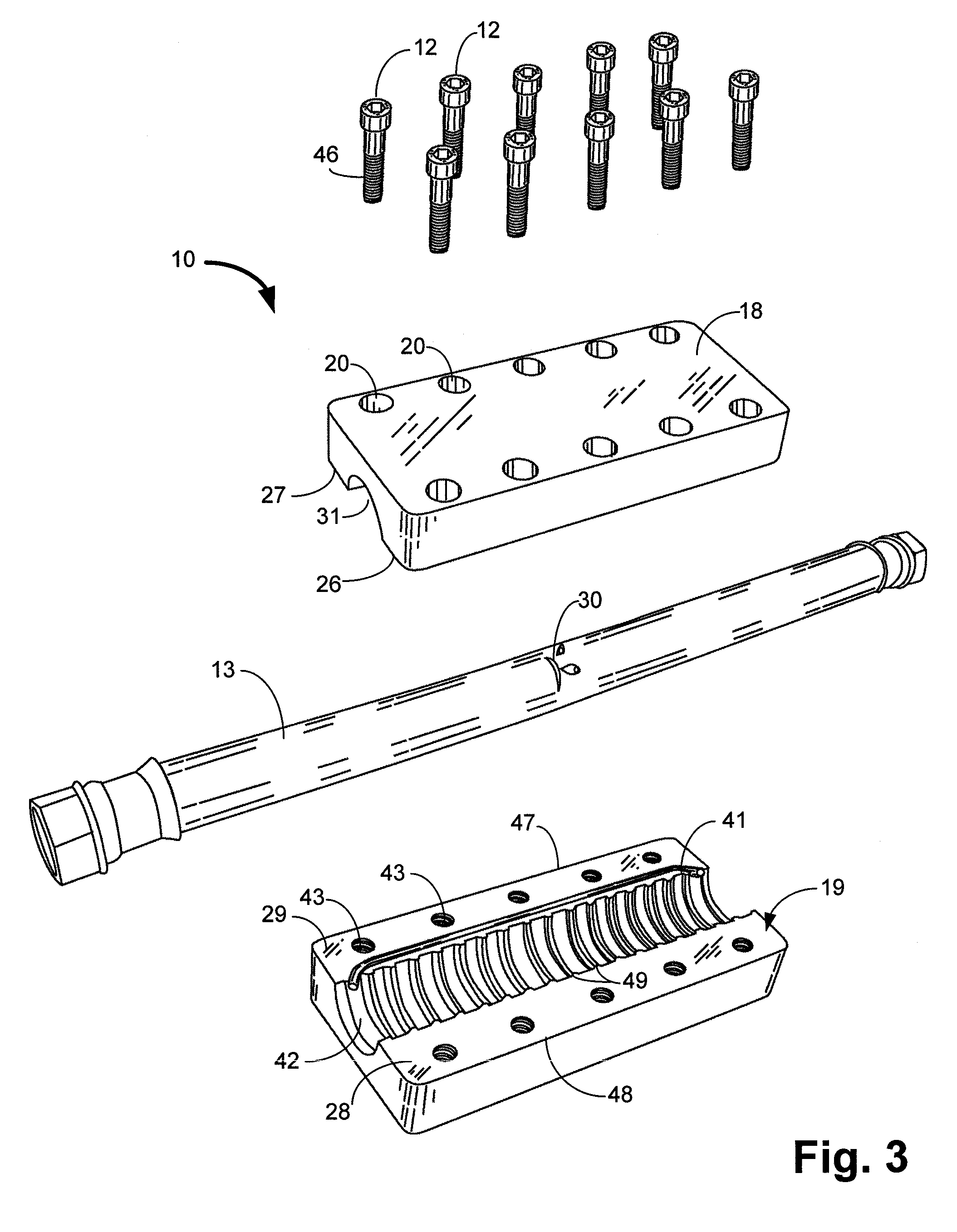
[0015]FIG. 1 is a top perspective view of a hose repair clamp 10 installed on a high pressure hose 13. The hose 13 is standard high pressure hydraulic hose that is known in the art. In one embodiment, the hose 13 is a 2- or 4-wire hydraulic hose, such as SAE 100R2AT hose. Hoses of this type typically have an inner layer (not shown) of synthetic rubber, a layer of braided wire (not shown), one or more layers of additional rubber and braided wire (not shown), and then an outermost layer 15 of rubber. Fittings 14 are disposed at opposing ends of the hose 13 for fastening the hose 13 to other devices.

[0016]The hose 13 is shown disposed within the hose repair clamp 10, which clamp 10 is installed to temporarily stop or slow leaks (not shown) in the hose. In this regard, the hose 13 is sandwiched between an upper clamp portion 18 and a lower clamp portion 19. The upper clamp portion 18 and the lower clamp portion 19 are joined together via a plurality of fasteners 12 to form a generally c...


PUM

PropertyMeasurementUnit
Timeaaaaaaaaaa
Pressureaaaaaaaaaa
Angleaaaaaaaaaa

Abstract

A hose clamp for repairing high pressure hydraulic hoses comprises a first clamp portion mated to a second clamp portion around a hose. The first and second clamp portions each comprise a semi-cylindrical channel extending longitudinally along an inner surface of the clamp. The hose is received within the channel and a plurality of fasteners releasably affix the clamp portions together. A plurality of barbs extending circumferentially around the channel compress the hose to minimize leakage from the hose.

Description

BACKGROUND AND SUMMARY OF THE INVENTION[0001]High pressure hydraulic hoses failing in use in the “field” cost time and money. Typically, a user must replace a leaky hydraulic hose before work can resume, as there are few, if any, known field repairs available for high pressure hydraulic hoses.[0002]The device according to the present disclosure comprises two clamp portions which “sandwich” a hose at the point of leakage. A semi-cylindrical channel extending along the inner surface of the clamp portions receives the hose and a plurality of fasteners fixes the two clamp portions together. Barbs extending into the channel protrude into the hose and seal against the outside rubber layer of the hose. Because the outside rubber layer of the hose is resilient, the barbs further cause the outside rubber layer to press against the inner hose layers. The compression of the barbs into the hose minimizes leakage longitudinally along the hose. Gasket seals extending along sealing surfaces of the...

Claims


Application Information

Patent Timeline
IPC IPC(8): F16L49/06
CPCF16L55/172
Inventor WILKINSON, TRAVIS T.
Owner HOSEBEE
Why Eureka
Try Eureka