System and method for thermographic inspection

Inactive Publication Date: 2012-11-01
GENERAL ELECTRIC CO
View PDF9 Cites 15 Cited by
  • Summary
  • Abstract
  • Description
  • Claims
  • Application Information

AI Technical Summary

Problems solved by technology
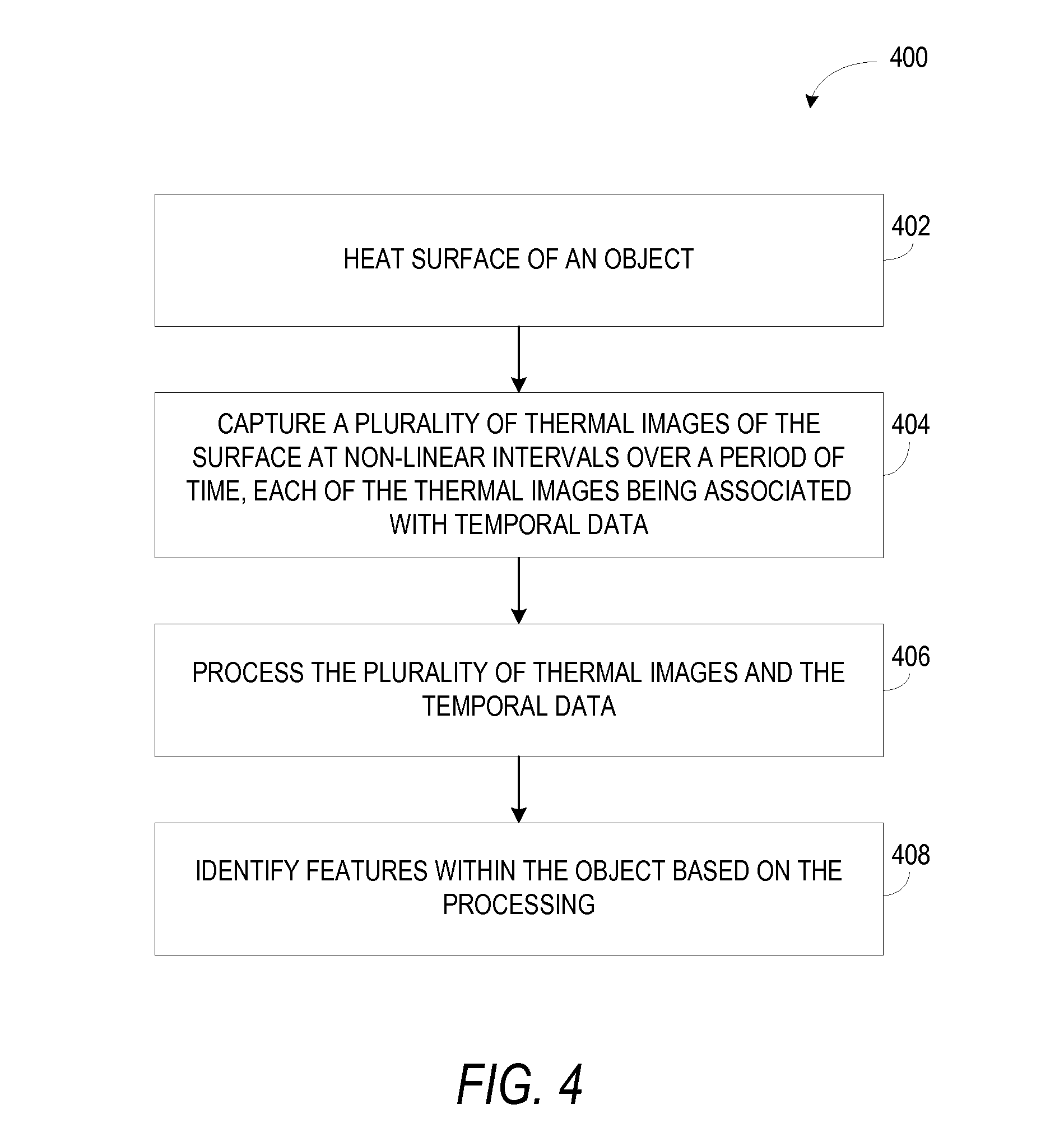
Such techniques are skill intensive and require much manual effort.
However, the thermal activity occurs at a non-linear rate.
This causes too few thermal images being captured at the beginning of the thermal transient, when the thermal activity is high, and too many thermal images (with a large proportion being redundant images) being captured at the end of the thermal transient when the th

Method used


Image

  • System and method for thermographic inspection
  • System and method for thermographic inspection
  • System and method for thermographic inspection

Examples


Embodiment Construction

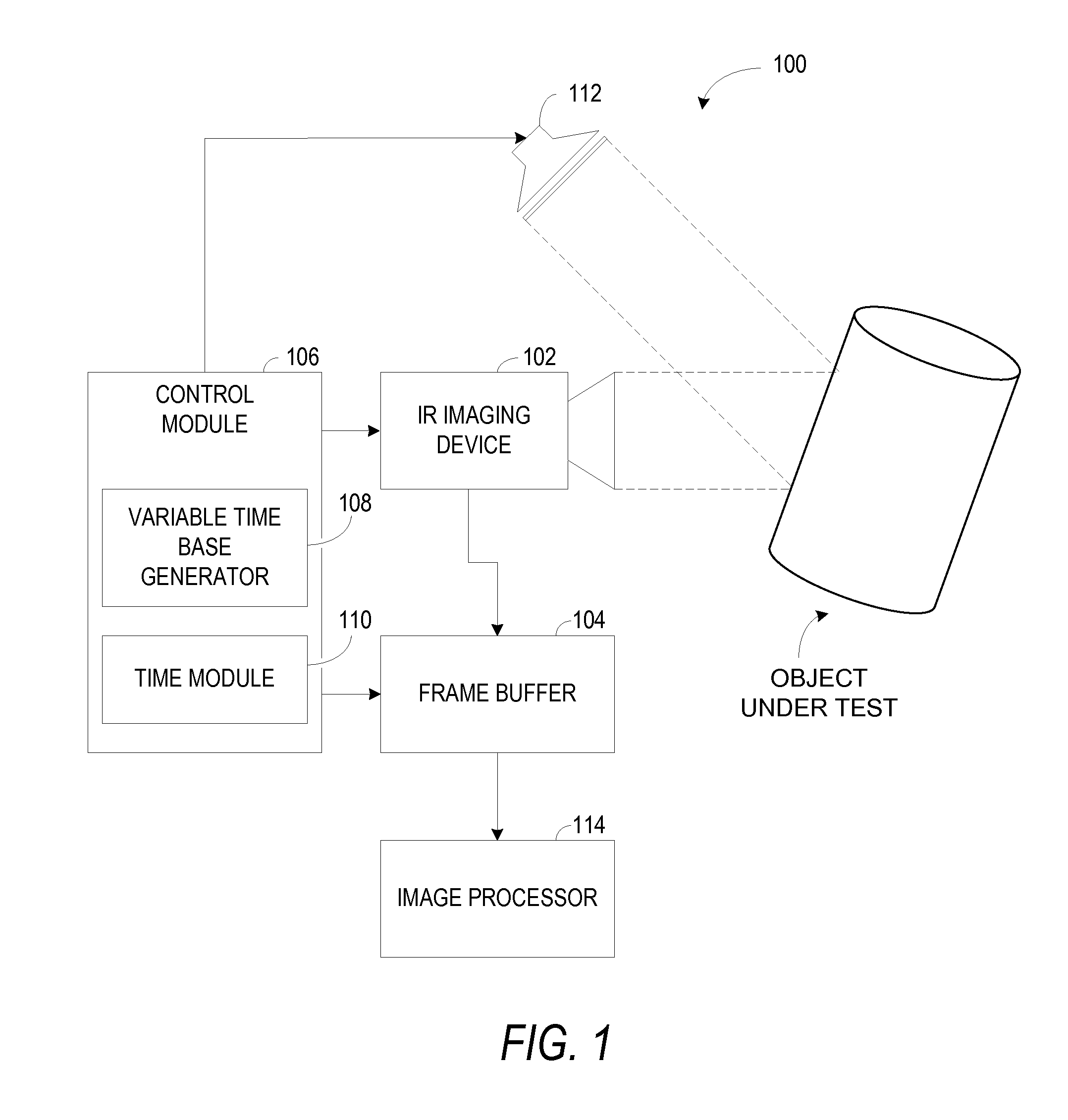
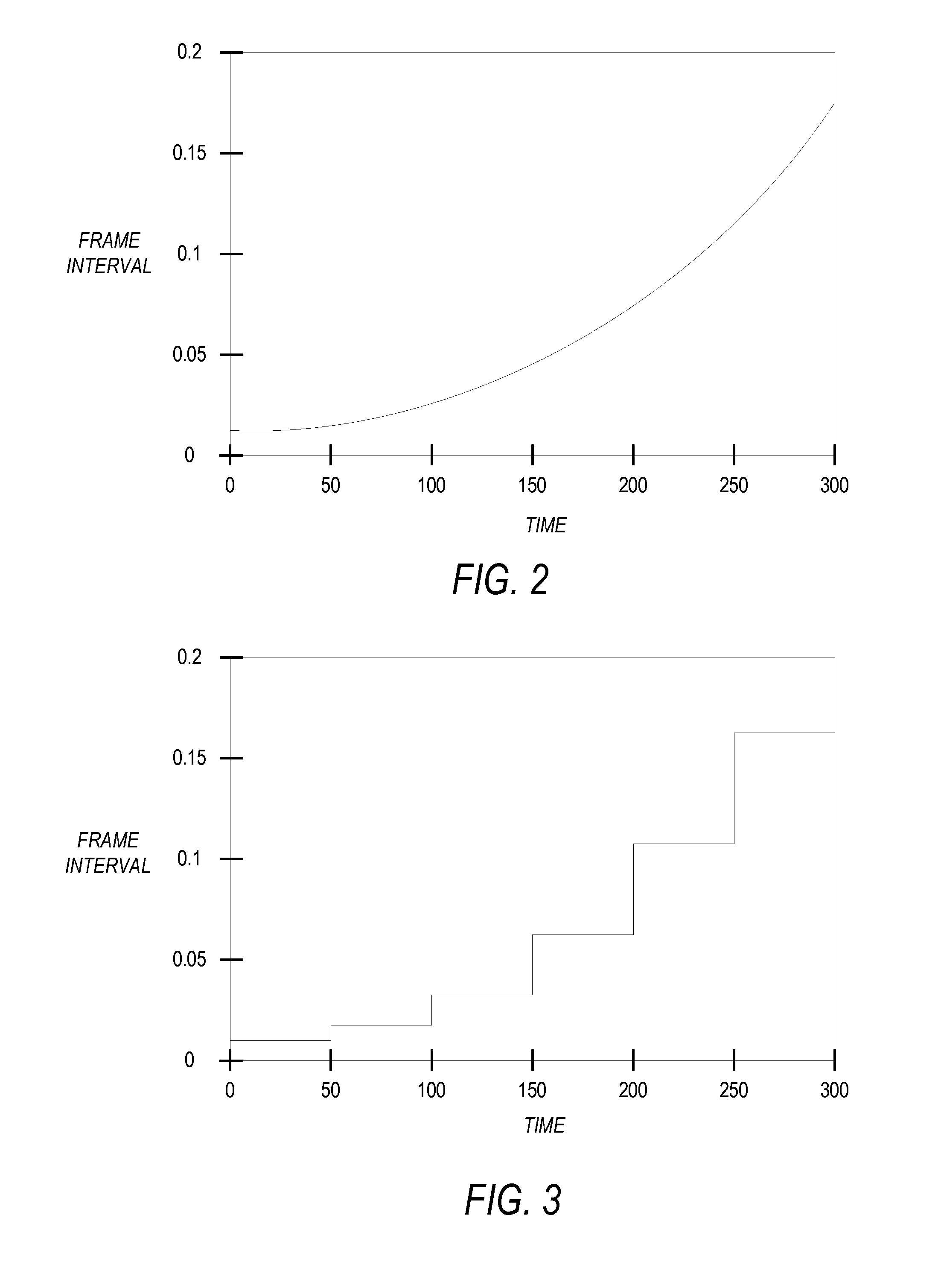
[0012]Embodiments of a thermographic imaging system are presented herein. The system employs a non-linear time base for triggering an infra red (IR) camera, to enable imaging at a non-linear rate. In transient thermographic testing, for example, the object under test is heated by a predefined temperature. Heating is then stopped and the object under test allowed to return to ambient temperature. During the thermal transient, thermal activity of the object under test takes place at a non-linear rate dependant on various factors such as, but not limited to, emissivity, absorptivity, reflectivity, and temperature of the object under test. Specifically, the thermal activity occurs rapidly at the beginning of the thermal transient, and slows down as the thermal transient progresses. Thus, imaging at the non-linear rate may reduce the number of redundant images, thus reducing requirements of processing power, buffer memory, and image file sizes. The system stores temporal data associated ...


PUM


Abstract

A method for thermographic imaging is described. The method captures a plurality of thermal images of a surface of an object, at non-linear intervals over a period of time, each of the thermal images being associated with temporal data. The method then processes the plurality of thermal images and the temporal data, and identifies features within the object based on the processing.

Description

BACKGROUND[0001]Embodiments presented herein relate generally to infra-red imaging, and more specifically to transient thermographic inspection.[0002]Thermographic inspection is the nondestructive testing of objects through imaging of thermal patterns on the object's surface. Thermographic inspection is often preferred to other nondestructive testing techniques such as ultrasonic inspection and radiographic inspection, for various advantages offered by thermographic inspection. Thermographic inspection is non-contact, non-intrusive, allows for detection of subsurface detects close to the surface, allows for inspection of large surfaces, and offers high speed inspection. One form of thermographic inspection is transient thermography. Transient thermography involves observing the temperature distribution on the surface of an object under test as it is subjected to a thermal transient such as a pulse of heat or a pulse of heat sink, and then allowed to return to ambient temperature. An...

Claims


Application Information

Patent Timeline
IPC IPC(8): H04N5/33
CPCG01N25/72H04N5/33H04N5/332G01N25/00H04N23/11
Inventor KNIGHT, BRYON EDWARDHOWARD, DONALD ROBERTRINGERMACHER, HARRY ISRAEL
Owner GENERAL ELECTRIC CO
Why Eureka
Try Eureka