Process cartridge
- Summary
- Abstract
- Description
- Claims
- Application Information
AI Technical Summary
Benefits of technology
Problems solved by technology
Method used
Image
Examples
first embodiment
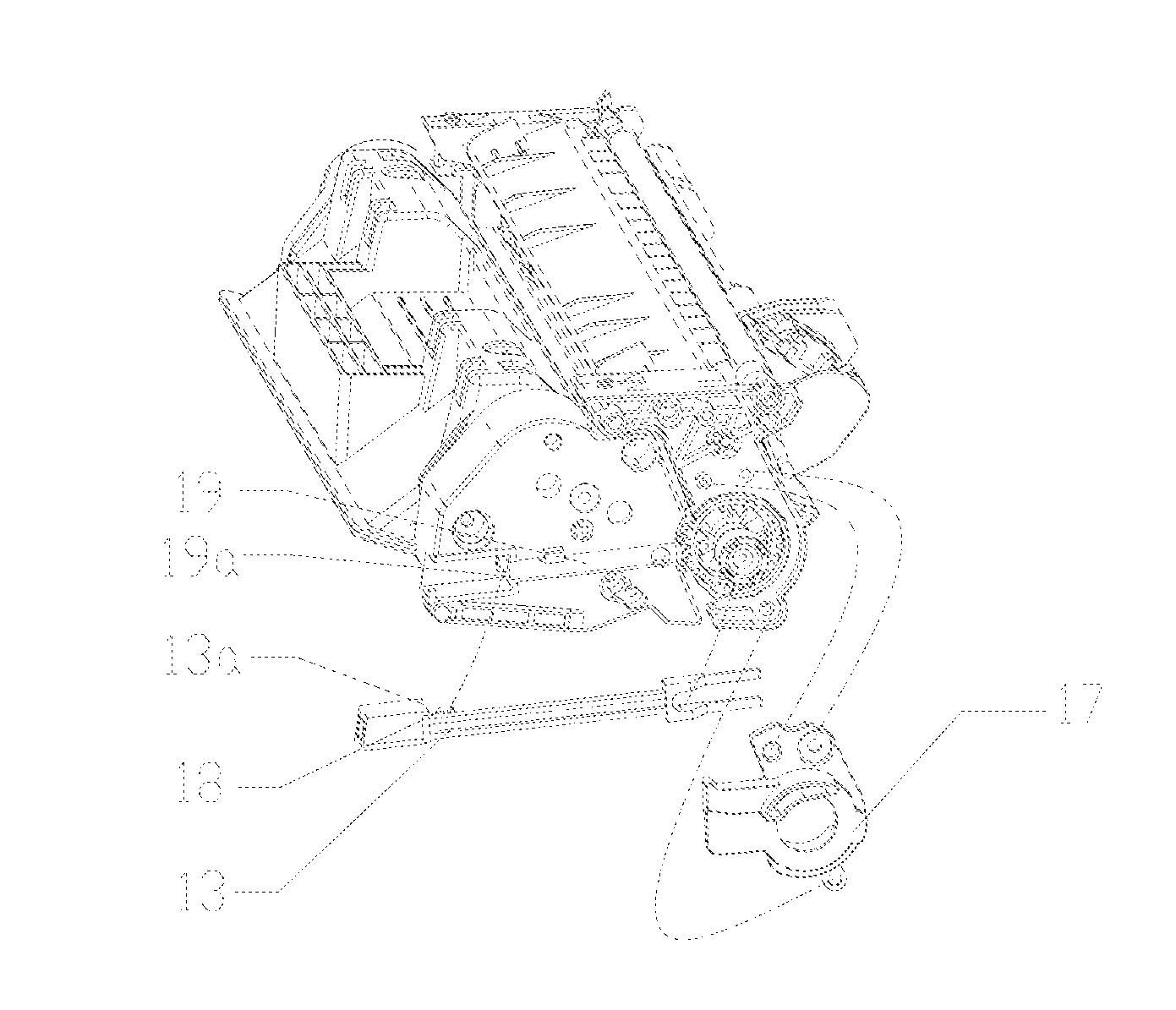
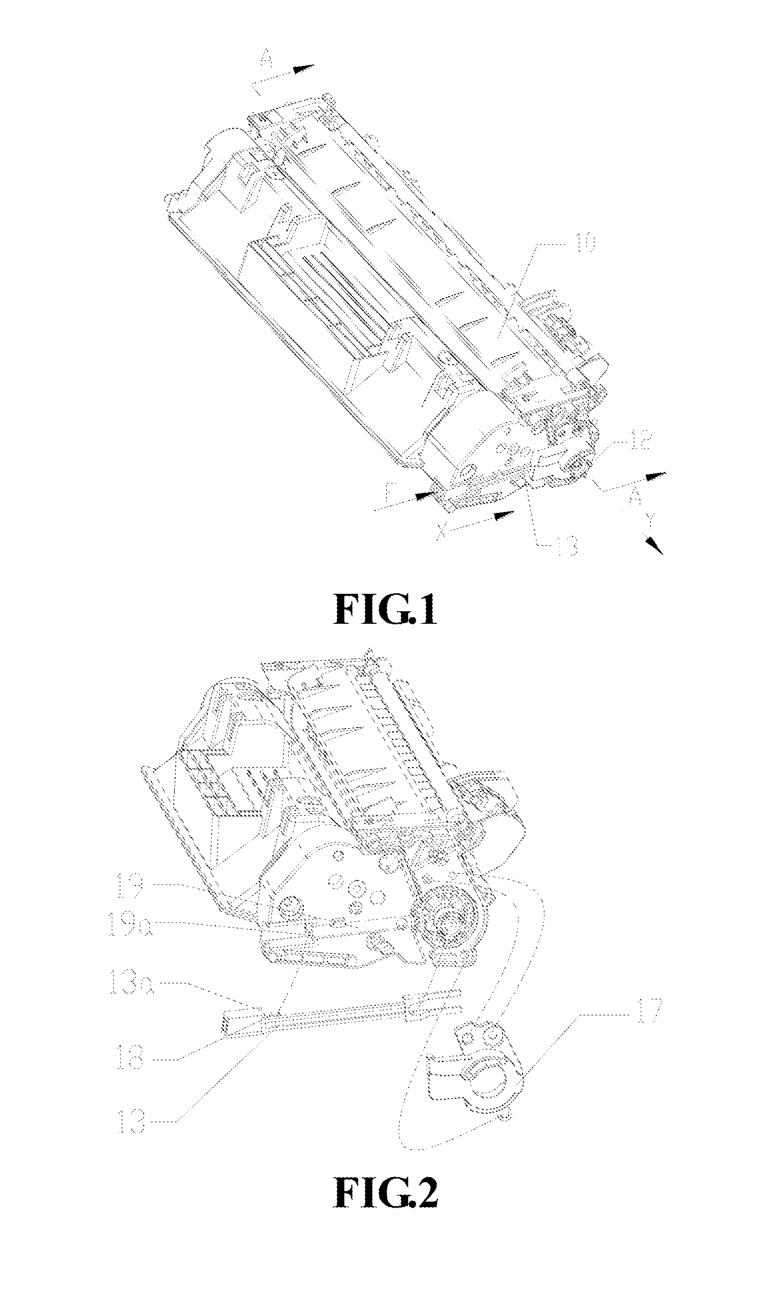
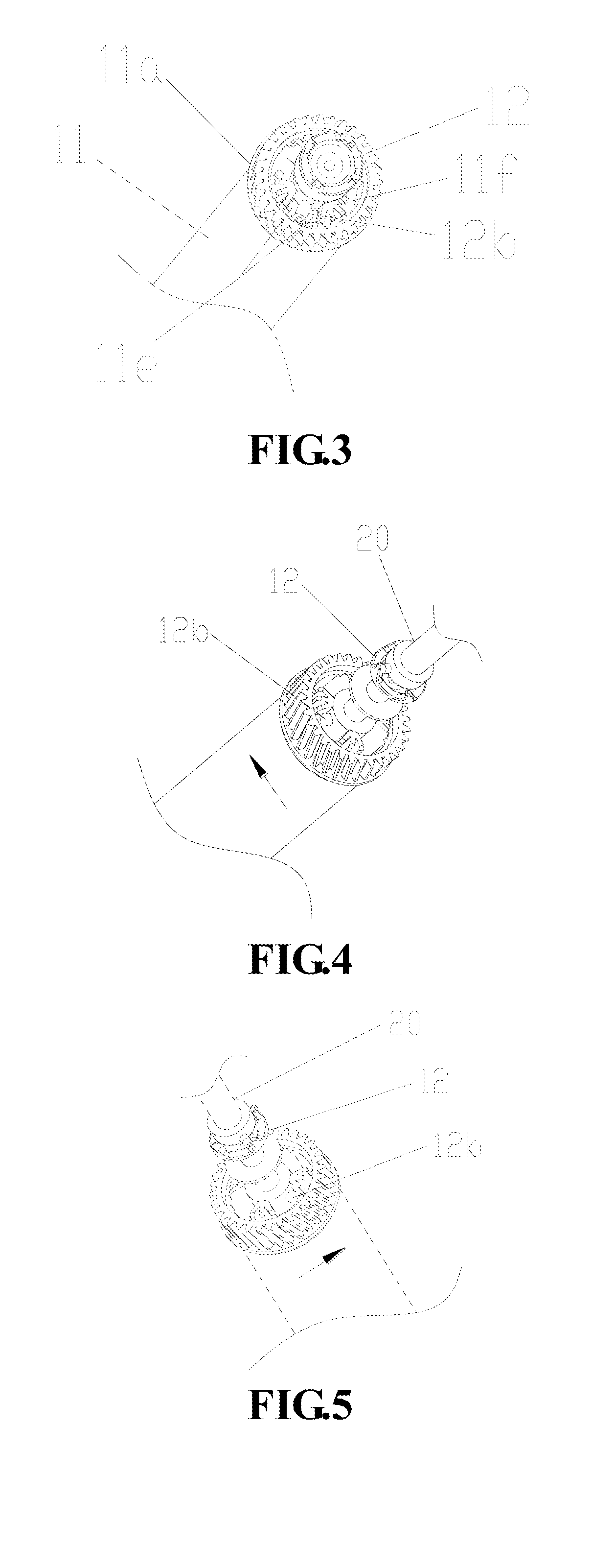
[0059]FIG. 1 is a stereogram of a process cartridge of a preferred embodiment of the invention, and FIG. 2 is an exploded view of the process cartridge illustrated in FIG. 1. As illustrated in FIG. 2, a press rod 13 and a first spring 18 are arranged at one side of a process cartridge housing 10, where a driving force receiving opening 12 is arranged; the press rod 13 and the first spring 18 are combined into a control mechanism; the press rod 13 is arranged inside a guide groove 19 on the process cartridge housing 10 and slides back and forth along the guide groove 19 in the X direction; and the first spring 18 leans against a space between an urging surface 13a of the press rod 13 and a leaning surface 19a of the guide groove 19 and provides an elastic restoring force for the press rod 13. When the process cartridge is positioned on an image forming device, the urging surface 13a of the press rod 13 tends to be far away from the leaning surface 19a when the press rod 13 is under t...
second embodiment
[0070]In the above embodiment, only the driving force receiving opening 12 can be driven by the press rod 13 to extend or retract in the axial direction of the photosensitive member 11 so as to engage or disengage with the driving mechanism 20 on the image forming device. It can be understood that a retractable mechanism in this embodiment can also adopt the mode that a driving force receiving opening 12 and a photosensitive member 11 are integrated into a whole and extended or retracted together, and the engagement and disengagement of the driving force receiving opening 12 and the driving mechanism 20 on the image forming device is controlled by a press rod 13. The structures which are the same with those of the first embodiment (such as a control mechanism) are not described in detail here.
[0071]The structure and the working process of the retractable mechanism are as follows:
[0072]As illustrated in FIG. 9, a shaft pin 14 and a support 17 are arranged on a process cartridge housi...
third embodiment
[0074]The structure and the operating process of a retractable mechanism in the embodiment, which is the same with those of the first and second embodiments, are not repeated here.
[0075]In the invention, the retraction of the driving force receiving opening can not only be realized by a mechanical press mode but also can be controlled by an electromechanical mode. The implementation of a control mechanism is as follows:
[0076]As illustrated in FIG. 15, the embodiment adopts a single-coil solenoid valve 4d to control the engagement and disengagement of a driving force receiving opening 5d at the driven side of a connecter 14d and a driving mechanism 6d of an image forming device. The driving force receiving opening 5d is arranged at one end of a shaft 8d of the connector 14d, and the other end of the shaft 8d of the connector 14d passes through a hollow cylinder of the solenoid valve 4d and can move left or right relative to the solenoid valve; the solenoid valve 4d is fixed on a proc...
PUM
 Abstract
Description
Claims
Application Information
 - R&D
- Intellectual Property
- Life Sciences
- Materials
- Tech Scout
- Unparalleled Data Quality
- Higher Quality Content
- 60% Fewer Hallucinations
Browse by: Latest US Patents, China's latest patents, Technical Efficacy Thesaurus, Application Domain, Technology Topic, Popular Technical Reports.
© 2025 PatSnap. All rights reserved.Legal|Privacy policy|Modern Slavery Act Transparency Statement|Sitemap|About US| Contact US: help@patsnap.com


